






Articles

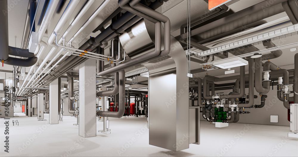
In vertical tower design, what MEP engineering solutions work best for high-rise residential buildings represents an intricate engineering challenge that directly impacts structural viability, occupant comfort, safety, and long-term asset value. Unlike low-rise or commercial properties, high-rise residential developments are vertical cities that operate continuously under extreme physical and environmental loads. As towers grow taller and more slender, mechanical, electrical, and plumbing (MEP) systems must overcome gravity, thermal buoyancy, wind shear, and lateral forces.
At the same time, these networks must facilitate individualized indoor environments, enforce strict code compliance, and satisfy ambitious green building standards. Designing these critical networks requires moving away from traditional, single-zone systems toward a framework of zoned distribution and digital coordination.
Evaluating What MEP Engineering Solutions Work Best for High-Rise Residential Buildings
Determining what MEP engineering solutions work best for high-rise residential buildings requires a detailed assessment of physical scale, microclimates, spatial constraints, and lifecycle costs. The choice is rarely about selecting the single most efficient component. Rather, it focuses on choosing an integrated system where the mechanical, electrical, and plumbing networks function collectively to mitigate vertical constraints.
Historically, developments utilized centralized systems with distributed control limits, often sacrificing energy efficiency to minimize upfront construction costs. Modern high-rise engineering, however, uses a decentralized-complexity paradigm. By distributing mechanical and plumbing functions into vertical zones while maintaining centralized safety and electrical supervision, modern high-rises achieve greater resilience, better part-load efficiency, and superior user comfort.
Standard 1: Mechanical Systems and Zoned HVAC Comfort
High-rise residential mechanical design must maintain indoor air quality and precise thermal control across distinct microclimates. A skyscraper’s upper floors experience higher wind velocities, lower ambient temperatures, and intense solar exposure compared to the sheltered lower floors. At the same time, the system must control internal pressures and maintain safe boundaries for indoor air circulation.
HVAC System Typologies: Water Source Heat Pumps, VRF, and Hydronic Solutions
Choosing between Variable Refrigerant Flow (VRF) systems, Water Source Heat Pumps (WSHP), Chilled Water systems, and Air-to-Water (ATW) monoblock heat pumps is one of the most important decisions in high-rise mechanical design.
Traditional air-source VRF systems use refrigerant as the direct thermal transport media. While VRF offers excellent zoning flexibility and high part-load efficiency, it faces challenges in high-rise residential applications due to lineset length limitations and strict safety codes. Under ASHRAE Standard 15 and UL 60335-2-40, the maximum allowable charge of A2L (mildly flammable) refrigerants is limited by the Effective Dispersal Volume Charge (EDVC) of the smallest occupied space. Because VRF systems route high-pressure refrigerant through vertical copper risers directly into small apartment bedrooms, a single pipe joint leak could release the entire system charge, exceeding safe flammability thresholds. Mitigating this requires expensive leak-detection networks, automated isolation valves, and protective shaft conduits, which drives up initial installation costs.
Decentralized Water Source Heat Pumps (WSHPs) bypass this issue. In a WSHP design, water is circulated through a closed condenser loop throughout the building, connected to a central cooling tower on the roof and a boiler in the basement. Individual, factory-sealed WSHP units are located within each apartment’s utility closet. This design confines the refrigerant entirely to the self-contained apartment unit, eliminating the risks of large-scale refrigerant leaks and long direct-expansion linesets. Furthermore, WSHPs reduce building energy consumption by up to 44% compared to standard air-source VRF systems in cold climates, and maintain high performance during extreme seasonal temperature swings.
Air-to-Water (ATW) monoblock heat pumps are also a growing alternative. Confining 100% of the refrigerant loop to the building’s exterior, ATW systems distribute hot or chilled water through simple hydronic lines inside the building envelope. This allows integrated domestic hot water heating and eliminates interior refrigerant safety concerns entirely, making it highly adaptable to future eco-friendly refrigerants like propane ($R\text{-}290$).
The technical differences between these prominent systems are analyzed below:
| Performance Parameter | Variable Refrigerant Flow (VRF) | Water Source Heat Pumps (WSHP) | Air-to-Water Monoblock (ATW) |
| Primary Transport Media | Refrigerant ($R\text{-}410A$ or $R\text{-}32$) | Condenser Loop Water | Hydronic Water (Chilled/Hot) |
| Safety Code Compliance | Complex (ASHRAE 15 / UL 60335-2-40 EDVC limits) | High (Refrigerant confined to factory-sealed units) | Maximum (Refrigerant isolated completely outdoors) |
| Max Line Length Limits | Rigid physical limits (Compressor oil return concerns) | Virtually unlimited (Governed by water pumping) | Unlimited (Governed by hydronic pumping) |
| Domestic Hot Water Integration | Requires separate independent heating system | Requires separate boilers or heat pump heaters | Fully integrated (Up to 50% higher than Energy Star UEF) |
| Low-Temperature Backup | Low efficiency (Relies on electric resistance elements) | High efficiency (Supported by central boiler loop) | Integrated hydronic backup within the water loop |
| Operational Control Model | Proprietary closed-source networks | Open-source building DDC / BACnet compatible | Open-source building DDC / BACnet compatible |
These configurations must be systematically integrated into the comprehensive HVAC layout plans to verify routing feasibility, shaft sizing, and equipment placement during the early schematic design phase.
Standard 2: High-Rise Ventilation and Indoor Air Quality Standards
In modern high-rise residential buildings, operable windows are often locked or limited due to extreme wind forces at high elevations. Consequently, mechanical ventilation is the primary means of ensuring acceptable indoor air quality (IAQ). To maintain a healthy living environment, designs must adhere strictly to residential ventilation standards. For instance, ASHRAE Standards 62.1 and 62.2 govern minimum ventilation rates to prevent contaminant buildup and manage moisture levels.
Under ASHRAE Standard 62.2, the whole-house mechanical ventilation rate ($Q_{fan}$) is calculated using the following formula:
$$Q_{fan} = 0.03 \cdot A_{floor} + 7.5 \cdot (N_{br} + 1)$$
Where:
- $Q_{fan}$ is the fan flow rate in liters per second ($\text{L/s}$).
- $A_{floor}$ is the interior floor area in square meters ($\text{m}^2$).
- $N_{br}$ is the number of bedrooms.
For IP units, the formula is expressed as:
$$Q_{fan} = 0.01 \cdot A_{floor} + 7.5 \cdot (N_{br} + 1)$$
Where the flow rate is measured in cubic feet per minute ($\text{cfm}$) and the floor area is in square feet ($\text{ft}^2$).
To minimize thermal losses and maintain tenant comfort, Dedicated Outdoor Air Systems (DOAS) with integrated Energy Recovery Ventilators (ERVs) are highly effective. ERVs transfer both sensible and latent heat between incoming fresh air and outgoing exhaust air, reducing the overall mechanical heating and cooling loads by 50% to 70% in humid or cold climates. In addition, modern IAQ standards have updated the filtration benchmark from MERV 6 to MERV 11, which requires powerful fan motors to overcome higher static pressure drops across denser filter media.
Controlling the Stack Effect: Physics, Formulas, and Mitigation Strategies
The stack effect is a significant challenges in high-rise HVAC engineering. Driven by density and temperature differences between indoor and outdoor air, the stack effect causes heated air to rise vertically through elevator shafts, stairwells, and utility runs during the winter. This creates negative pressure at the building’s base, drawing cold air in, and positive pressure at the top, forcing warm air out.
The driving pressure differential ($\Delta P$) across the building envelope at any height can be calculated using the classic stack effect equation:
$$\Delta P = C \cdot h \cdot \left(\frac{1}{T_o} – \frac{1}{T_i}\right)$$
Where:
- $\Delta P$ is the pressure difference ($\text{Pa}$).
- $C$ is the physical constant, equal to $3460$ in SI units (and $7.64$ in IP units).
- $h$ is the vertical distance from the neutral pressure plane ($\text{m}$ or $\text{ft}$).
- $T_o$ is the absolute outdoor temperature ($\text{K}$ or $^\circ\text{R}$).
- $T_i$ is the absolute indoor temperature ($\text{K}$ or $^\circ\text{R}$).
The elevation of the Neutral Pressure Plane (NPP), where indoor and outdoor pressures are equal, is defined by the vertical distribution of leakage paths. For a tower with uniform envelope leakage, the NPP is expressed as:
$$h_{NPP} = \frac{H}{1 + \left(\frac{A_t}{A_b}\right)^2}$$
Where:
- $H$ is the total height of the building ($\text{m}$).
- $A_t$ is the cumulative leakage area at the top of the structure ($\text{m}^2$).
- $A_b$ is the cumulative leakage area at the bottom ($\text{m}^2$).
A 60-story building ($180\text{ m}$) experiencing a $40^\circ\text{C}$ winter temperature differential can generate over $90\text{ Pa}$ of pressure difference. This pressure can cause elevator doors to malfunction, generate whistling noises, and make exit doors difficult to open, often exceeding the $67\text{ N}$ limit mandated by accessibility standards.
To control these forces, engineers use several key mechanical design solutions:
- Variable Corridor Pressurization: Rather than distributing outdoor air uniformly, the DOAS is designed to deliver higher air volumes to the lower floors where infiltration pressure is highest. This creates a $+15\text{ to }+25\text{ Pa}$ positive pressure barrier, while higher floors require less pressurization ($+5\text{ to }+10\text{ Pa}$) to prevent forcing interior air outward through the facade.
- Inline Supply Fans at fresh air intakes: Installing a dedicated, variable-speed inline supply fan (typically $1/4\text{ HP}$ per suite) at the fresh air inlet of each unit ensures positive ventilation regardless of stack-effect fluctuations.
- Floor-to-Floor Firestopping: Properly rated floor-to-floor firestopping along plumbing risers, electrical conduits, and structural voids limits vertical air movement, reducing stack effect drafts.
The operational parameters for stack effect mitigation are structured below:
| Vertical Zone | Physical Pressure Dynamic | Targeted Mechanical Pressurization | Airflow Strategy |
| Upper Floors | Positive Pressure (Exfiltration Zone) | $+5\text{ to }+10\text{ Pa}$ corridor-to-exterior | Reduced makeup air; exfiltration assists ventilation |
| Mid-Building | Neutral Pressure Plane Area | $+8\text{ to }+15\text{ Pa}$ corridor-to-exterior | Balanced makeup air matching localized exhaust |
| Lower Floors | Negative Pressure (Infiltration Zone) | $+15\text{ to }+25\text{ Pa}$ corridor-to-exterior | Maximum makeup air to offset chimney suction |
Standard 3: Electrical Load Distribution and Smart Integration
High-rise residential buildings are vertical load centers. Delivering megawatts of power from the utility vault to individual apartment panels requires distribution networks designed to minimize voltage drop, control heat rise, and simplify future modifications.
Cable Risers vs. Busway Systems: The Engineering Evaluation
High-current vertical distribution typically involves choosing between traditional insulated copper cables in conduit or prefabricated Busbar Trunking Systems (Busways/Bus Ducts).
For vertical distribution loads exceeding $800\text{ A}$, cable systems become physically bulky and electronically inefficient. A $2000\text{-amp}$ feeder run requires multiple parallel cables per phase, necessitating large, multi-tier cable trays (often spanning $24\text{ inches}$ wide) and extensive conduit bending. In contrast, a $2000\text{-amp}$ prefabricated bus duct measures only $10\text{ inches} \times 8\text{ inches}$, saving over $25\%$ of physical shaft space.
Furthermore, busway systems conform to strict international safety standards, such as IEC 61439-6, which governs design, installation, and routine testing parameters. Under IEC 61439-6, busways are verified to withstand high short-circuit faults (typically $50\text{ to }150\text{ kA}$ peak withstand, $I_{pk}$) and manage thermal performance under full-load conditions. Because the metallic enclosure of a bus duct provides superior heat dissipation, it operates cooler than cable trays ($55\text{-}65^\circ\text{C}$ temperature rise above ambient compared to $70\text{-}80^\circ\text{C}$ for cables in conduit). This prevents thermal derating of the conductors, yielding significant lifecycle energy savings.
A structured comparison of these two systems is presented below:
| Engineering Metric | Cable and Conduit Systems | Busbar Trunking Systems (Busway) |
| Footprint in Vertical Shafts | Large (Requires wide cable trays or multiple conduits) | Compact (Requires $25\%$ less envelope space) |
| Voltage Drop & Power Loss | Higher ($2.5\text{-}3\%$ at full load; higher impedance) | Lower ($1.5\%$ at full load; low-impedance design) |
| Thermal Characteristics | Higher heat retention ($70\text{-}80^\circ\text{C}$ operating rise) | High dissipation ($55\text{-}65^\circ\text{C}$ operating rise) |
| Conductor Derating Factor | Requires $15\text{-}20\%$ derating in bundled conduits | Maintains full rated ampacity under standard load |
| Installation Labor Hours | High ($400\text{-}500$ hours for equivalent vertical runs) | Low ($200$ hours; prefabricated plug-and-play sections) |
| Modification / Tap Flexibility | Difficult (Requires splicing or installing junction boxes) | Simple (Plug-in tap-off units added in minutes) |
| Material Life Cycle & Recycling | Lower (30-year life; difficult to recycle PVC insulation) | High (50-year life; 95% recyclable copper/aluminum) |
By engaging specialized electrical engineering services, developers can analyze potential fault levels, design harmonic mitigation filters, and plan coordinated overcurrent protection systems to prevent localized faults from disrupting power to the rest of the building.
Smart Metering and Backup Power Infrastructure
Tenant-level utility accountability is crucial in modern multi-family towers. Smart metering systems integrated directly into localized distribution panels or busway tap-off boxes allow the building automation system to track real-time power metrics. This setup enables automated billing and peak load management.
Emergency backup generators (typically diesel or dual-fuel natural gas) are essential for life-safety compliance. They must feed dedicated distribution branches via Automatic Transfer Switches (ATS). These branches power critical building services, including:
- Stairwell and elevator shaft pressurization fans.
- Fire pumps and standpipe pressure-boosting systems.
- Emergency egress lighting and communication systems.
- Primary passenger elevators for firefighter evacuation operations.
Standard 4: Hydraulic Design, Pressure Zoning, and Water Efficiency
Plumbing systems in tall residential structures face a fundamental challenge: water has significant physical weight. Designing a domestic water system that delivers reliable, hygienic water to the top floor while preventing excessive pressure on the lower levels requires detailed calculations and careful zoning.
Pressure Zoning and the Limit of Static Pressure
The pressure exerted by a standing column of water is directly proportional to its height. This static head pressure ($P_{static}$) is calculated using the following formula:
$$P_{static} = 0.433 \cdot H$$
Where:
- $P_{static}$ is the static pressure in pounds per square inch ($\text{psi}$).
- $H$ is the total height of the standing water column in feet ($\text{ft}$).
In metric terms, static column pressure rises by approximately $0.1\text{ bar per meter}$ of vertical fall (or $1\text{ bar}$ per three floors).
Under the International Plumbing Code (IPC Section 604.8), the maximum static water pressure at any standard plumbing fixture is strictly capped at $80\text{ psi}$ ($552\text{ kPa}$). Pressures above $80\text{ psi}$ cause fixture damage, high water consumption, splashing, and severe water hammer. Conversely, to operate luxury fixtures like rainfall showerheads and flushometer valves, the system must maintain a minimum residual flow pressure of $15\text{ to }20\text{ psi}$ ($105\text{ to }140\text{ kPa}$) at the highest, most hydraulically remote fixture.
To balance these requirements in a tower exceeding $100\text{ ft}$, the building must be divided into vertical pressure zones, typically capped at 5 to 7 floors ($15\text{ to }22\text{ m}$). This design ensures that the bottom fixture in each zone stays below $80\text{ psi}$ static while the top fixture maintains the required minimum residual pressure.
Layout Architectures: Upfeed VFD Boosters vs. Downfeed Break Tanks
Engineers typically use three primary hydraulic distribution models in high-rise buildings:
- Downfeed from Overhead Tanks (OHT): Water is pumped to a main rooftop storage tank and flows downward via gravity. While highly reliable during power outages, it adds significant structural loads to the roof and consumes premium terrace space.
- Downfeed with Master Pressure-Reducing Valves (PRVs): A single basement booster pump forces water to the top floor, using PRVs to drop the pressure on the lower floors. Although popular with speculative developers due to lower initial installation costs, this is an energy-inefficient plumbing design. It expends energy to pump water to the highest dynamic head, only to dissipate that pressure as friction across lower-level PRVs. In addition, high pressure drops across PRV seats lead to accelerated wear, valve chatter, and frequent maintenance requirements.
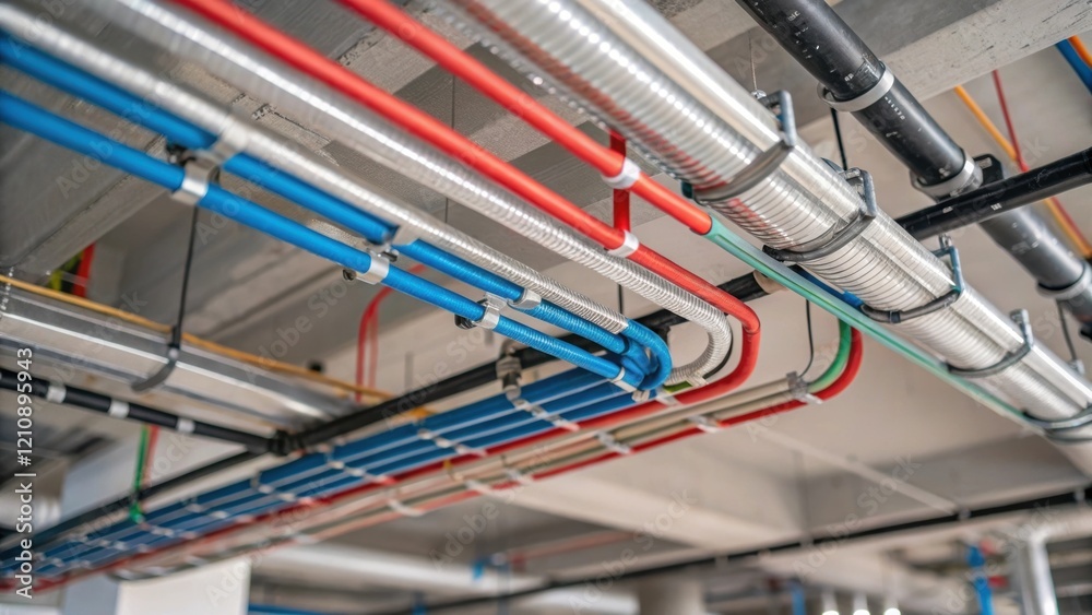
- Multi-Zone VFD Upfeed Booster Systems: High-efficiency, vertical multistage pumps are configured in parallel to serve individual pressure zones directly from basement break tanks. Equipped with Variable Frequency Drives (VFDs), these pumps adjust their speed in real-time to match actual building water demand, reducing energy consumption by up to 50% compared to constant-speed systems. Multi-pump systems are designed with $N+1$ redundancy, allowing one pump to be isolated for maintenance without affecting building supply.
A structured comparison of these three layout architectures is detailed below:
| System Characteristic | Direct Gravity Downfeed (OHT) | Downfeed with Master PRVs | Multi-Zone VFD Upfeed Booster |
| Energy Efficiency | Moderate (Constant bulk pumping, gravity delivery) | Very Low (High energy input wasted across PRV seats) | High (VFD modulates speed based on real-time demand) |
| Structural Load Impact | High (Heavy rooftop water storage tanks required) | Low (Basement-centered equipment) | Low (Basement-centered equipment) |
| Maintenance Profile | Low (Simple mechanical floats, low component wear) | High (Frequent PRV seat failures and seal leaks) | Low (VFD soft-starts reduce pipe wear and stress) |
| Footprint Impact | High (Consumes premium rooftop real estate) | Low (Compact basement pump footprint) | Moderate (Requires space for multi-pump skids) |
| Pressure Stability | High (Consistent static gravity head pressure) | Moderate (Subject to downstream PRV lag) | High (Precise, tunable VFD pressure control) |
| Power-Outage Resilience | Maximum (Gravity tank storage delivers water without power) | Low (Relies entirely on generator power) | Low (Relies entirely on generator power) |
For development teams aiming to balance architectural aesthetics, structural weight, and energy performance, selecting the proper pressure zones and equipment configurations is a vital step. Utilizing professional MEP plan services during the schematic design phase ensures that the selected hydraulic strategy meets municipal requirements and fits within the project’s spatial constraints.
High-Rise Sanitary Drainage and Venting Systems
Sanitary drainage in high-rise buildings presents challenges related to fluid velocity and pneumatic pressures. Wastewater falling down a vertical drainage stack accelerates until it reaches terminal velocity—approximately $15\text{ feet per second}$ ($4.5\text{ m/s}$)—where frictional resistance matches gravitational pull. At vertical-to-horizontal transitions, such as at the base of the stack, this high-velocity flow slows down, creating a hydraulic jump that can fill the horizontal pipe and block airflow.
If the venting system is inadequate, these flow fluctuations can cause pneumatic imbalances. Positive pressure ahead of falling water can blow out fixture traps on lower floors, while negative pressure behind it can siphon traps on upper floors, allowing sewer gas to enter residences. To prevent this, plumbing designers utilize dedicated relief vents, yoke vents, and specialized single-stack systems like Sovent aerator fittings, which break up the falling water column and maintain pressure equilibrium inside the stack.
Standard 5: Fire Protection and Life Safety Systems
Fire safety in high-rises is highly complex due to prolonged evacuation times and limitations on firefighting ladders. Life safety systems must detect, compartmentalize, suppress, and control fires using integrated building systems.
NFPA 14 Standpipe Classifications and Design Targets
NFPA 14 governs the installation of standpipe and hose systems in tall structures. High-rise buildings require Class I standpipes for professional firefighter use, consisting of $2\frac{1}{2}\text{-inch}$ hose connections located in fire-rated exit stairwells.
The system must satisfy these key hydraulic parameters:
- Minimum Residual Flow Pressure: The system must deliver a minimum residual pressure of $100\text{ psi}$ ($6.9\text{ bar}$) at the hydraulically most remote $2\frac{1}{2}\text{-inch}$ hose outlet while flowing water.
- Minimum Design Flow Rate: The required flow is $500\text{ GPM}$ ($1893\text{ L/min}$) for the most remote riser, plus $250\text{ GPM}$ ($946\text{ L/min}$) for each additional riser, up to a maximum system cap of $1000\text{ GPM}$ ($3785\text{ L/min}$) for fully sprinklered towers.
- Maximum Connection Pressure: To ensure the safety of emergency responders, the static and residual pressure at any hose connection is strictly limited to $175\text{ psi}$ ($12.1\text{ bar}$). Where the static pressure exceeds $175\text{ psi}$, an approved pressure-regulating device (PRV) must be installed to limit the pressure under both static and flowing conditions.
Managing System Pressure and the 300 psi Boundary
Because static pressure increases by $0.433\text{ psi per vertical foot}$ ($0.098\text{ bar per meter}$), a standpipe water column in a tall building generates extremely high pressures at the base. NFPA 14 limits standpipe system zones to a maximum working pressure of $350\text{ psi}$ based on standard component pressure limits. System valves, check-valves, and fittings are typically rated to a maximum working pressure of $350\text{ psi}$, while sprinkler components and hose valves are often rated to $175\text{ psi}$.
An industry-standard threshold of $300\text{ psi}$ serves as a critical design boundary. Standard fire department pumpers are limited in their discharge pressure capabilities. If a standpipe zone requires more than $300\text{ psi}$ at the street-level Fire Department Connection (FDC) to supply the top floor, the building must incorporate automated building-based redundancy. This requires:
- On-site fire pump systems dedicated to that specific high-pressure zone.
- Intermediate water storage tanks (break tanks) to reset the static pressure to zero.
- Dedicated emergency power distribution branches to fire pumps.
- Fully automatic controls that do not rely on fireground pumper operations to meet the required residual flow pressure.
A summary of standpipe and life safety system design parameters is provided below:
| System Metric | Class I Standpipe System | Class II Standpipe System | Class III Combined System |
| Primary User | Professional Firefighters | Building Occupants | Both Occupants & Firefighters |
| Hose Connection Size | $2\frac{1}{2}\text{ inches}$ ($65\text{ mm}$) | $1\frac{1}{2}\text{ inches}$ ($40\text{ mm}$) | Both $1\frac{1}{2}\text{ in}$ and $2\frac{1}{2}\text{ in}$[cite: 43] |
| Min Residual Pressure | $100\text{ psi}$ ($6.9\text{ bar}$) | $65\text{ psi}$ ($4.5\text{ bar}$) | $100\text{ psi}$ ($2\frac{1}{2}\text{ in}$) / $65\text{ psi}$ ($1\frac{1}{2}\text{ in}$) |
| Min Riser Flow Rate | $500\text{ GPM}$ ($1893\text{ L/min}$) | $100\text{ GPM}$ ($379\text{ L/min}$) | $500\text{ GPM}$ ($1893\text{ L/min}$) |
| Max Hose Connection Static | $175\text{ psi}$ ($12.1\text{ bar}$) | $175\text{ psi}$ ($12.1\text{ bar}$) | $175\text{ psi}$ ($12.1\text{ bar}$) |
| Max Hose Valve Residual | $175\text{ psi}$ (Requires PRV above limits) | $100\text{ psi}$ (Requires PRV above limits) | $175\text{ psi}$ ($2\frac{1}{2}\text{ in}$) / $100\text{ psi}$ ($1\frac{1}{2}\text{ in}$) |
| Max Zone System Pressure | $350\text{ psi}$ (Unless express risers used) | $350\text{ psi}$[cite: 30] | $350\text{ psi}$[cite: 30, 44] |
Advanced Interdisciplinary Coordination and BIM Execution
High-rise residential developments are spatially constrained, which requires detailed coordination among engineering and architectural disciplines. Structural shear walls, vertical columns, lateral wind bracing, elevator shafts, garbage chutes, and heavy utility runs must all fit within a compact central core.
┌─────────────────────────────────────────────────────────────────────────┐
│                    3D BIM Clash Detection Protocol                      │
├─────────────────────────────────────────────────────────────────────────┤
│                                                                         │
│  [Architectural Model] ───┐                                             │
│                           │                                             │
│  [Structural Model] ──────┼───► [Navisworks Collision Detection] ───► CD │
│                           │                                             │
│  [MEP Systems Model] ─────┘                                             │
│                                                                         │
└─────────────────────────────────────────────────────────────────────────┘
Implementing 3D Building Information Modeling (BIM)
To resolve spatial conflicts before construction begins, designers rely on 3D Building Information Modeling (BIM). Using tools with high Levels of Detail (typically LOD 350 or LOD 400), coordination software runs clash-detection checks to locate physical interference between systems. Common examples include:
- Horizontal HVAC supply ducting intersecting with structural post-tensioned floor slabs.
- Gravity-sloped sanitary sewers clashing with lateral steel wind-bracing beams.
- High-current electrical busway runs crossing hydronic heating or cooling lines.
BIM models also simplify the design of prefabricated vertical utility risers and horizontal corridor racks. Off-site prefabrication can accelerate construction schedules by up to 50% and reduce on-site labor installation costs by 20%.
Managing Project Schedules and Construction Budgets
Coordinating large-scale high-rise construction requires structured scheduling and financial tracking. Standard manual progress reporting can be overly optimistic, which often leads to project delays. Modern project managers address this by using digital scheduling tools and operational digital twins. These platforms run simulations of various construction scenarios, predicting potential material bottlenecks and labor inefficiencies.
Additionally, using 3D laser-scanning technology to document accurate, as-built conditions is a key step in major renovation or historic retrofit projects. This ensures new MEP components integrate correctly with existing structural elements, reducing the need for costly field adjustments.
Strategic Recommendations for Design Teams
Optimizing high-rise residential MEP systems requires balancing physical constraints with occupant comfort and energy efficiency. Based on fluid dynamics, thermal buoyancy, electrical physics, and international fire codes, several key strategic directives are recommended for design teams:
- Specify Water-Loop Condenser or Air-to-Water HVAC Systems: Avoid long vertical VRF copper linesets carrying high-pressure refrigerant through residential units. Confine refrigerants to self-contained apartment heat pumps (WSHPs) or exterior monoblocks (ATWs) to ensure safety code compliance and minimize leakage risks.
- Control Stack Drafts Dynamically: Utilize a central DOAS with variable corridor pressurization—delivering higher air volumes to lower levels—combined with localized inline supply fans to ensure stable pressure boundaries throughout the building envelope.
- Implement Prefabricated Busway Systems for Main Risers: For electrical distribution above $800\text{ A}$, transition from traditional cables to busways to save shaft space, reduce voltage drop, and ensure thermal and short-circuit compliance under standards like IEC 61439-6.
- Design Multi-Zone, VFD-Driven Hydraulic Distribution: Avoid single-booster, PRV-heavy plumbing layouts that waste energy. Use vertical pressure zoning with multi-pump vertical multistage VFD assemblies to protect terminal fixtures while maintaining reliable pressure control.
- Adhere strictly to the $300\text{ psi}$ NFPA 14 Standpipe Boundary: If a standpipe zone exceeds $300\text{ psi}$ of required head, implement building-based redundancy—such as on-site fire pumps and intermediate gravity break tanks—to protect occupants and emergency responders.
By partnering with an experienced MEP design firm, development teams can ensure that these technical solutions are fully tailored to the project’s unique height, layout, and regulatory requirements. Engaging specialized MEP plan services from the earliest stages of schematic design ensures that all mechanical, electrical, plumbing, and life-safety systems work together to deliver a safe, efficient, and future-proof vertical community.







