

Articles

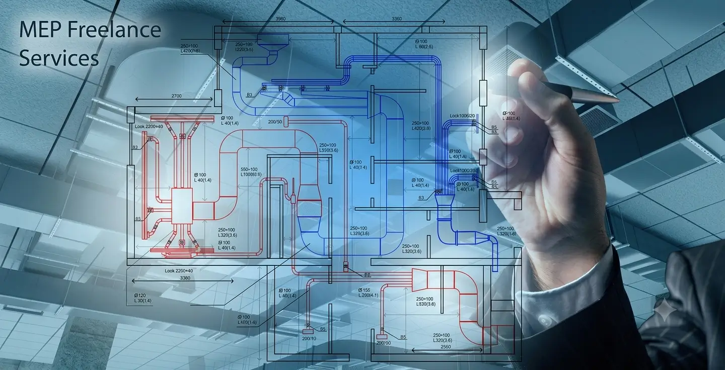
Across complex infrastructure projects, high-precision mep cad drafting services serve as the foundational framework connecting engineering design intent with physical field execution. As modern commercial, industrial, and residential structures demand increasingly dense service distribution networks within constrained ceiling plenums and vertical utility shafts, standardized drafting protocols become essential for project viability. Delivering precise technical drawings minimizes design ambiguities, enforces regional code compliance, and establishes an integrated digital workflow between multidisciplinary engineering teams. Modern project execution relies heavily on structured methodologies offered by professional engineering platforms such as EngrTeam, where comprehensive MEP plan services bridge conceptual engineering and field-ready construction documentation.
The technical integration of Computer-Aided Design (CAD) and Building Information Modeling (BIM) has transformed building service coordination from 2D manual drawing overlays into high-fidelity, multi-dimensional modeling frameworks. Adhering to standardized layer naming conventions, precise Level of Development (LOD) definitions, and structured Common Data Environments (CDE) drives quantifiable productivity gains—often improving construction productivity by up to 15% and compressing delivery schedules by 20%.
Standardized Layering Frameworks in MEP CAD Drafting Services
A fundamental requirement of professional mep cad drafting services is the implementation of standardized, non-conflicting CAD layering protocols. In large-scale multi-consultant environments, unstandardized drawing files lead to line-weight distortion, reference file (XREF) misalignment, and severe visual clutter during discipline coordination. Modern technical drafting primarily relies on two globally recognized CAD layering frameworks: the American Institute of Architects (AIA) CAD Layer Guidelines—incorporated into the National CAD Standard (NCS)—and the international ISO 13567 standard.
The National CAD Standard structures layer names into hierarchical data fields separated by hyphens. The mandatory two-character Discipline Designator defines the primary engineering domain (such as M for Mechanical, E for Electrical, P for Plumbing, or F for Fire Protection). This is followed by a mandatory four-character Major Group representing the specific physical system (such as DUCT for ductwork, PIPE for piping, or CABL for cable trays). Optional four-character Minor Groups further detail the layer contents (such as HIGH for high-pressure systems or DIMS for annotations), while a single-character Status field designates construction phases (such as N for new work or E for existing structures to remain). For example, the layer identifier M-DUCT-LOWR-DIMS-N unambiguously indicates new mechanical low-pressure ductwork dimensions.
Conversely, the ISO 13567 standard utilizes a fixed-length bit-string field structure designed for universal programmatic parsing across diverse CAD software platforms. ISO 13567 divides layer identifiers into mandatory fields—such as the responsible agent (A for architect, M for mechanical engineer) and graphic element type—and optional fields detailing physical building sectors, vertical story levels, drawing scale, and work packages. Enforcing these standard layering structures within organizational CAD templates guarantees seamless data exchange between structural engineers, architects, and MEP trade contractors, eliminating cross-disciplinary file corruption during background updates.
| Technical Parameter | AIA / National CAD Standard (NCS) v5.0 | ISO 13567 Standard |
| Primary Structural Format | Delimited alphanumeric hierarchy (Discipline-Major-Minor-Status) | Fixed-length, continuous bit-string alpha-numeric field code |
| Field Separators | Hyphen (-) separating distinct data fields | No character separators; relies on strict character position |
| Mandatory Fields | Discipline Designator (2 chars), Major Group (4 chars) | Responsible Agent (2 chars), Element Graphics/Text type (2 chars) |
| Optional Fields | Two Minor Groups (4 chars each), Status/Phase (1 char) | Status (1 char), Sector (4 chars), Phase (1 char), Scale (1 char) |
| Mechanical Ductwork Layer Example | M-DUCT-LOWR-TEXT-N (Mechanical, Low-Pressure Duct, Text, New) | H-E-00-T- (HVAC Agent, Element Graphics, Ground Floor, Text) |
| Electrical Cable Tray Layer Example | E-CABL-TRWY-DIMS-N (Electrical, Cable Tray, Dimensions, New) | E-E-01-D- (Electrical Agent, Element Graphics, First Floor, Dimensions) |
| Plumbing Drainage Layer Example | P-PLUM-SANR-PIPE-N (Plumbing, Sanitary Drainage Pipe, New) | P-E-00-E- (Plumbing Agent, Element Graphics, Ground Floor, Elements) |
Core Engineering Disciplines Covered by MEP CAD Drafting Services
Executing complex building designs demands specialized domain knowledge across mechanical, electrical, plumbing, and fire protection engineering sub-fields. Each sub-discipline requires specific schematic representation rules, regional code compliance mandates, and standardized annotation conventions.
HVAC and Mechanical System Layouts
Mechanical HVAC drafting establishes the distribution pathways for conditioned air, hydronic heating, and chilled water networks. Drafting teams produce detailed construction layouts adhering strictly to technical standards established by the Sheet Metal and Air Conditioning Contractors’ National Association (SMACNA) and the American Society of Heating, Refrigerating and Air-Conditioning Engineers (ASHRAE).
Drafting technicians construct full-scale ductwork routes detailing sheet metal gauges, joint connections (such as TDC/TDF flanges), turning vanes, acoustic lining, volume control dampers (VCDs), and fire/smoke dampers (FSDs). Every duct segment includes clear elevation callouts specifying Top of Duct (TOD) and Bottom of Duct (BOD) offsets relative to structural finished floor levels. Air distribution networks are engineered to transition smoothly from main high-static air handling unit (AHU) supply headers down to variable air volume (VAV) terminal boxes, flexible duct runs, and supply air diffusers.
Engineers rely on fluid dynamic calculations during drafting to evaluate static pressure drops and velocity constraints. The velocity pressure P_v within a rectangular duct section is evaluated using the fluid mechanics relation:
Where rho represents the air density approx 1.2 under standard atmospheric conditions) and represents the mean airflow velocity in meters per second (m/s). To calculate friction losses across non-circular rectangular ducts during routing adjustments, drafting teams compute the equivalent circular duct diameter De using the Huebscher equation:
Where a and b represent the interior physical dimensions of the rectangular duct sides. For specialized mechanical distribution design, engineering teams rely on tailored HVAC layout plan documentation to maintain static pressure balance and ensure energy-efficient system performance.
Electrical Power, Lighting, and Distribution Networks
Electrical CAD drafting spans high-voltage power distribution, low-voltage control systems, interior and exterior lighting schemes, emergency backup circuits, and grounding networks. Electrical layouts require detailed single-line diagrams (SLDs), riser diagrams, cable tray routing, and panelboard load schedules. Power routing originates from high-voltage utility service risers, feeding main switchboards (MSB) and step-down transformers, which distribute branch circuits through distribution panelboards down to localized lighting modules, power receptacles, and low-voltage data busways.
Drafting teams incorporate physical equipment clearance envelopes mandated by the National Electrical Code (NEC) or regional regulatory frameworks. For instance, switchboards and distribution panelboards require a minimum working clearance depth (typically 36 / 914 mm) and continuous uninhibited width in front of live electrical components. Furthermore, electrical drafting dictates spatial separation between high-voltage power conduits and sensitive low-voltage communication or data cable trays to prevent electromagnetic interference (EMI). Detailed technical layouts are further refined through dedicated electrical engineering services to guarantee compliance with transformer heat dissipation and circuit protection standards.
Plumbing and Sanitary Drainage Systems
Plumbing CAD drafting covers domestic cold and hot water supply systems, sanitary drainage, waste and vent (DWV) piping, storm water management, and specialized medical gas networks. Unlike pressurized water distribution lines, gravity-fed DWV lines impose strict physical routing constraints due to continuous slope requirements. Sanitary drainage lines are drafted with precise pitch gradients (typically frac in/ft or frac{1}{4} , equivalent to 1\% – 2\% slopes) originating from fixture traps down through vertical soil stacks to building exit drains.
Drafting teams indicate exact Invert Elevations (IE), pipe wall thickness, insulation wrap dimensions, cleanout access points, and sleeve penetration details through load-bearing concrete beams or foundation floor slabs. Plumbing shop drawings generated from 3D CAD models provide field installers with precise spool sheets for off-site pipe cutting, fitting welding, and assembly tagging.
Fire Protection and Suppression Systems
Fire protection drafting encompasses active fire suppression systems, including wet and dry pipe sprinkler networks, pre-action deluge systems, standpipe risers, and fire pump rooms. Drafting specialists position sprinkler heads according to hazard classifications defined by National Fire Protection Association (NFPA) standards (such as NFPA 13, 14, and 20). Drawings indicate pipe schedules, hydraulic branch sizing, tamper switches, zone control valve assemblies, and main drain connections. Sprinkler main routing requires close spatial coordination with structural framing and overhead mechanical ductwork to maintain uninterrupted spray patterns and required vertical clearances beneath deflectors.
| System Category | Governing Technical Standards | Standard CAD Graphic Annotations | Key Maintenance Clearance Rules |
| HVAC & Ventilation | SMACNA Duct Standards, ASHRAE 62.1 & 90.1 | Airflow arrows, TOD/BOD elevations, CFM capacities, duct sizing | 24 \text{ in } (600 \text{ mm}) filter removal envelope around AHUs and VAV access doors |
| Electrical Power | NEC (NFPA 70), IEEE Regulations, IEC Standards | Circuit home runs, panelboard tags, conduit trade sizes, wire counts | 36 \text{ in } (914 \text{ mm}) uninhibited depth in front of switchgear and panelboards |
| Plumbing & DWV | IPC (International Plumbing Code), UPC, ASME | Pipe slope percentages, invert elevations (IE), nominal diameters, flow arrows | 18 \text{ in } (450 \text{ mm}) clearance around drainage cleanouts for snake rod access |
| Fire Protection | NFPA 13 (Sprinklers), NFPA 14 (Standpipes), NFPA 20 | Head type symbols, coverage radii, main pipe sizes, zone valve tags | 18 \text{ in } (450 \text{ mm}) vertical clearance beneath sprinkler deflector heads |
Level of Development Specifications in MEP CAD Drafting Services
The structured progression of technical drawings across project lifecycle phases is defined by the Level of Development (LOD) specification framework maintained by BIMForum and the American Institute of Architects (AIA). In mep cad drafting services, LOD specifications dictate the degree of geometric accuracy, spatial precision, and non-graphical attribute data embedded within system models as project information matures.
The LOD framework advances sequentially through six recognized milestones:
- LOD 100 (Conceptual Design): Building service systems are represented as generic spatial masses or volumetric zone reservations. Equipment capacity targets and major shaft pathways are approximated without specific geometric dimensions.
- LOD 200 (Schematic Design): MEP components are drafted as generic assemblies with approximate shapes, quantities, sizes, and orientations. Placeholder geometry indicates general equipment footprints and main riser routes.
- LOD 300 (Design Development): Systems are accurately modeled as specific geometric assemblies with precise dimensions, absolute spatial locations, routing orientations, and system connections. Ductwork, piping, and cable trays reflect actual cross-sectional profiles and engineering capacities.
- LOD 350 (Construction Documentation & Coordination): Drafting extends to cross-disciplinary interface details. Models include physical mounting hangers, seismic sway braces, structural wall sleeves, insulation thickness wraps, and dedicated access/clearance envelopes necessary for field installation.
- LOD 400 (Off-Site Fabrication & Assembly): Components are drafted as detailed fabrication-level assemblies. Models include exact sheet metal gauges, flange joint connections, spool piece breakdowns, individual pipe weld locations, manufacturer-specific equipment part numbers, and shop assembly tags.
- LOD 500 (As-Built Field Verification & Facilities Management): Final deliverables reflect field-verified, actual conditions following physical construction completion. Geometric models incorporate operational asset management data—including equipment maintenance schedules, commissioning logs, serial tags, and COBie data fields.
| LOD Phase | Geometric Precision | Embedded Data Attributes (LOI) | Primary Utility | Typical Deliverables |
| LOD 100 | Conceptual spatial volumes | Target area loads 2CFM/sq ft | Massing & shaft planning | Spatial allocation diagrams |
| LOD 200 | Generic system profiles | System classification tags | Preliminary spatial fit | Schematic single-line plans |
| LOD 300 | Precise physical geometry | Specific manufacturer ratings | Multidisciplinary design | Design intent drawings |
| LOD 350 | Includes supports & sleeves | Interface connection specs | Clash-free coordination | Coordinated shop drawings |
| LOD 400 | Fabrication-ready parts | Part numbers, weld maps | Off-site prefabrication | Spool sheets & BOQs |
| LOD 500 | As-built field verified | Asset IDs, warranty dates | Facility operations (FM) | As-built record drawings |
Spatial Coordination and Clash Detection Workflows in MEP CAD Drafting Services
A core advantage of deploying advanced mep cad drafting services within a 3D CAD or BIM environment is automated clash detection and multi-trade spatial coordination. Consolidating architectural, structural, and MEP trade models into a federated coordination workspace allows potential spatial conflicts to be identified and resolved digitally before site mobilization.
Classification of Coordination Clashes
Spatial coordination workflows classify system conflicts into three distinct operational categories:
- Hard Clashes: Occur when two physical components occupy the same 3D spatial geometry (for example, a 400 mm chilled water pipe penetrating directly through a load-bearing concrete structural beam).
- Soft (Clearance) Clashes: Occur when an element encroaches upon mandatory operational, safety, or maintenance access zones (for example, a cable tray routed directly under a valve handle, preventing technician access, or ductwork positioned too close to a sprinkler head).
- Workflow (4D) Clashes: Occur when temporal sequencing conflicts arise on site (for example, scheduling ceiling enclosure trades before overhead high-level ductwork and medical gas piping installation is completed).
The 8-Step Clash Resolution Cycle
Executing rigorous spatial coordination follows an eight-stage iterative cycle governed by structured information management procedures:
First, multi-disciplinary models (architectural, structural, mechanical, electrical, plumbing) are imported into a shared coordination platform using unified project origin coordinates. Misaligned origins result in severe report corruption, generating thousands of false conflicts. Second, system elements are isolated into distinct operational selection sets (such as Main Supply Ducts, High-Pressure Hydronic Pipes, or Low-Voltage Cable Trays). Third, specific spatial clear distances and geometric tolerances are assigned to selected system pairs based on design phase requirements.
Fourth, automated clash engines execute geometric overlap algorithms across designated selection sets. Fifth, false positives (such as flexible duct connections touching duct collars or pipes passing through pre-approved slab sleeves) are filtered out, leaving legitimate actionable issues. Sixth, valid clashes are logged into issue-tracking databases using BIM Collaboration Format (BCF) files, assigning ownership to specific trade contractors alongside mandatory resolution deadlines. Seventh, responsible trade designers adjust system routing in their authoring software following established priority hierarchies. Eighth, updated models are re-federated and re-tested to confirm conflict resolution without introducing secondary downstream clashes.
System Priority Hierarchy
When resolving spatial conflicts between overlapping trade services within confined ceiling plenums, drafting teams adhere to a strict priority hierarchy based on physical design flexibility and fluid dynamics:
Unpressurized gravity systems (such as sanitary drainage and storm water lines) maintain the highest priority because they cannot be diverted horizontally without violating mandatory slope rules. High-volume rigid supply and exhaust ductwork hold the second highest priority, as rerouting large sheet metal ducts introduces major friction losses and static pressure drops. High-voltage electrical busducts and heavy cable trays occupy the third tier due to rigid bend radii and high material costs. Pressurized fluid piping systems (such as domestic water, chilled water, and gas lines) occupy the fourth tier, as pressurized pipes can accommodate localized offset loops around obstructions using standard fittings without losing operational efficiency. Small-diameter flexible electrical conduits and signal cabling occupy the lowest priority tier due to their high routing adaptability.
To maintain global interoperability across these coordination steps, project teams utilize open data exchange standards managed by buildingSMART International, such as Industry Foundation Classes (IFC / ISO 16739).
| Primary Trade System | Secondary Trade System | Clash Classification | Hard Tolerance | Soft/Clearance Tolerance | Priority Precedence Rule |
| HVAC Supply Ductwork | Concrete Structural Beams | Hard Clash | 0 mm systems (such as domestic water) | 50 mm 2 in insulation gap | Structural integrity prevails; duct must lower or split |
| Sanitary Drainage Pipe | Main Cable Tray Riser | Hard / Soft | 0 \text{ mm } (0 \text{ in}) | 150 \text{ mm } (6 \text{ in}) safety clearance | Gravity drainage prevails; cable tray diverts horizontally |
| Electrical Cable Tray | Domestic Water Piping | Soft Clearance | N/A | 300 \text{ mm } (12 \text{ in}) above water line | Cable trays must pass above wet lines to avoid leak damage |
| Fire Sprinkler Pipe | HVAC Return Ductwork | Hard Clash | 0 \text{ mm } (0 \text{ in}) | 25 \text{ mm } (1 \text{ in})head clearance | Ductwork reroutes; sprinkler head retains code grid |
ISO 19650 Governance and Common Data Environments for MEP CAD Drafting Services
Modern mep cad drafting services operate within standardized international information management structures governed by the ISO 19650 standard series. ISO 19650 provides an internationally recognized framework for managing digital building asset data across design, construction, and operational phases.
The central pillar of ISO 19650 information governance is the Common Data Environment (CDE)—a centralized digital repository controlled by strict access permissions, standardized file naming conventions, and revision control workflows. Information within a CDE moves sequentially through four structured states:
- Work in Progress (WIP) State: Unverified technical drawings and models generated by specific trade design teams. Access is restricted strictly to the authoring discipline.
- Shared State: Verified CAD/BIM deliverables uploaded for multidisciplinary coordination and clash detection. Models in this state allow other consultants to reference updated background geometry.
- Published State: Formally authorized and approved deliverables suitable for construction execution, off-site procurement, or regulatory sign-off.
- Archived State: Historical record of all superseded file versions, transaction logs, and formal project submittals, providing a complete audit trail throughout the asset lifecycle.
Advanced Off-Site Prefabrication Driven by MEP CAD Drafting Services
High-precision mep cad drafting services drive modern industrial construction methodologies, including Design for Manufacture and Assembly (DfMA) and off-site prefabrication. Producing fabrication-ready LOD 400 CAD models enables mechanical contractors to transition from traditional manual site assembly to factory-controlled modular manufacturing.

Spool Drawings and Sheet Metal Cutting Schedules
From coordinated 3D CAD models, drafting teams automatically extract individual pipe spool drawings and automated sheet metal cutting schedules. Pipe spools detail exact cut lengths, fitting dimensions, weld seam locations, pressure test tags, and hanger mounting positions. Factory technicians assemble these sub-components under controlled manufacturing conditions, drastically reducing site labor hours and material waste.
Modular Racks and Skid Systems
For service-dense structures like data centers, hospitals, and high-rise commercial towers, drafting teams generate detailed shop drawings for multi-trade utility racks and skid-mounted central cooling plants. Multi-trade racks combine chilled water piping, supply/return ductwork, electrical cable trays, and fire protection mains into integrated steel framework assemblies that are trucked to site and hoisted into ceiling spaces as unified modules.
For retrofit and renovation projects, drafting teams utilize Point Cloud to CAD workflows. Terrestrial 3D laser scanners capture existing structural and spatial geometry with millimeter precision. Drafting specialists import these point cloud datasets into CAD authoring environments to create accurate as-built baseline models, mitigating spatial collision risks prior to installing new modular equipment skids.
Financial Optimization and Risk Mitigation via MEP CAD Drafting Services
Deploying high-precision mep cad drafting services directly targets the leading causes of budget overruns and schedule delays in commercial construction. Uncoordinated spatial designs and late field-level change orders can increase total project construction costs by 5% to12%.
By resolving spatial clashes during design coordination, engineering teams eliminate costly field re-work. The financial impact of design modifications increases exponentially as a project progresses through construction phases:
- Design Coordination Phase: Identifying a spatial conflict during CAD modeling costs approximately $100 in drafting adjustment time.
- Field Installation Phase: Resolving the same conflict on site after material procurement costs approximately $3,500 in field cutting, idle crew labor, and material scrap.
- Post-Concrete Pour Phase: Core-drilling structural slabs or re-fabricating concrete shear walls to accommodate missed pipe penetrations can exceed $15,000 per occurrence, while introducing long-term structural risks.
To consistently achieve these savings, structured CAD quality management relies on systematic validation checklists before releasing deliverables to construction teams. Engineering managers verify that shared world coordinate origins are aligned across disciplines, standard layer naming conventions are enforced, SMACNA duct pressure classes are met, NEC equipment clearances are respected, and hard/soft clashes are resolved.
Strategic Conclusions for Infrastructure Delivery
The systematic implementation of standardized mep cad drafting services is essential for navigating the spatial and operational complexities of modern building infrastructure. Transitioning from unstructured 2D drafting to rigorous, code-compliant, multi-dimensional modeling frameworks ensures seamless inter-disciplinary coordination, eliminates expensive field rework, and accelerates project schedules.
By enforcing standard CAD layering conventions, adhering to explicit Level of Development specifications, and integrating spatial coordination within ISO 19650 Common Data Environments, engineering firms establish a robust digital thread across the entire asset lifecycle. Ultimately, investing in precise, high-fidelity MEP drafting delivers predictable build costs, optimizes off-site prefabrication potential, and guarantees long-term operational excellence for complex facilities.







