

Articles

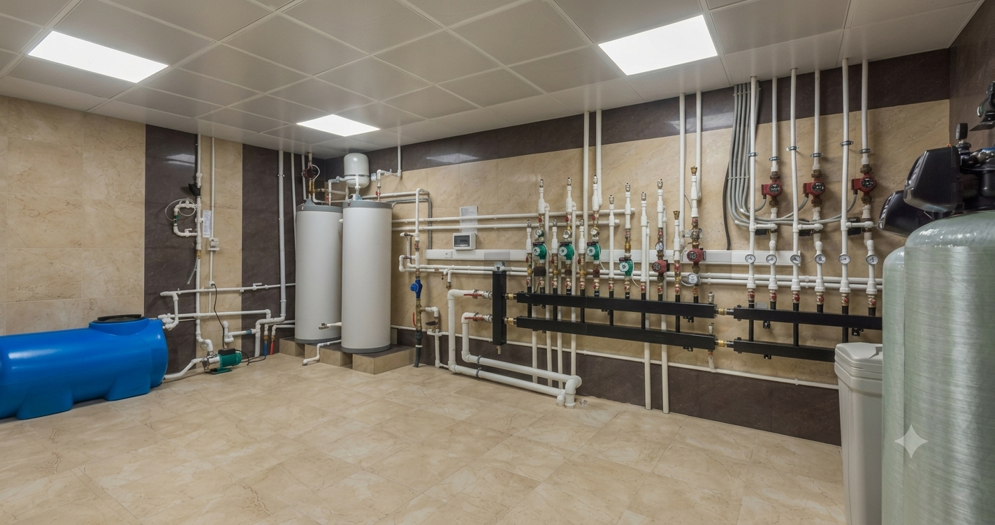
In modern civil and mechanical engineering, plumbing design services represent a foundational discipline that ensures public health, occupant safety, thermal efficiency, and environmental compliance across the built environment. The engineering of fluid conveyance systems encompasses fluid mechanics, thermodynamics, regulatory compliance, and virtual design construction (VDC) workflows. Rather than serving as a basic exercise in pipe layout, high-performance plumbing engineering demands precise mathematical modeling of hydraulic flows, transient surge pressures, self-cleansing velocities, and multi-trade spatial integration. As urban centers adopt higher building densities and non-standard architectural forms, plumbing systems must be designed to maintain operational resilience and minimize lifecycle capital expenditure.
Modern digital delivery relies on Building Information Modeling (BIM), parametric design tools, and automated clash detection software to integrate fluid systems into complex building assemblies. Designing these networks requires strict adherence to international standards, including ISO 19650 for digital information management, ISO 13567 for computer-aided design (CAD) layering, and standard plumbing codes published by the International Code Council (ICC) and the International Association of Plumbing and Mechanical Officials (IAPMO). A robust engineering strategy synthesizes sanitary drain, waste, and vent (DWV) systems with domestic hot water distribution, rainwater harvesting, stormwater management, and specialized fire suppression systems.
1. Hydraulic Sizing Principles in Advanced Plumbing Design Services
Accurate hydraulic sizing forms the core of high-performance plumbing design services. Oversized piping networks increase upfront material costs and elevate thermal distribution losses while creating stagnant, low-velocity zones that encourage bio-film accumulation and microbial growth such as Legionella pneumophila. Conversely, undersized distribution lines generate elevated fluid velocities that induce structural vibration, fluid-borne noise, accelerated erosion-corrosion, water hammer surges, and pressure drops at terminal fixtures. To establish optimal pipe diameters, engineering teams utilize standardized fixture unit methodologies to calculate peak coincident water demand rather than assuming total connected load.
Water Supply Modeling and Probabilistic Sizing in Plumbing Design Services
Water supply networks rely on the Water Supply Fixture Unit (WSFU) metric to evaluate potential system loading. Originating from empirical research conducted by Roy B. Hunter at the National Bureau of Standards (NBS BMS65), the “Hunter Curve” applies probability theory to predict peak water demand across diverse building occupancies. Hunter’s model assumes that fixture usage is intermittent and calculates peak demand at the 99th percentile, providing reliable system operation without unnecessary oversizing.
In contemporary computational design, non-linear equations convert accumulated fixture unit loads into estimated design flow rates (Q) expressed in gallons per minute (GPM) or liters per second (L/s). For general building water distribution, the relationship between total WSFU and design flow rate is expressed through power-law formulations derived from Hunter’s binomial distribution curves:
Qsupply = 0.013 × (WSFU)^0.555
Similarly, peak discharge rates within gravity drainage networks are calculated from Drainage Fixture Units (DFU) using the following power relationship:
Qdrainage = 0.0084 × (DFU)^0.613
Fluid velocity (v) within distribution piping is evaluated using the fundamental continuity equation:
v = Q/A = 4Q / (π × d²)
To mitigate acoustic transmission and pipe degradation, fluid velocities are generally capped at 8 ft/s (2.4 m/s) for cold water distribution lines, and 5 ft/s (1.5 m/s) for circulating domestic hot water networks operating above 140°F (60°C). Pressure loss across distribution runs is evaluated using the empirical Hazen-Williams equation:
hf = (10.67 × L × Q^1.852) / (C^1.852 × d^4.871)
Where hf is total friction loss (meters), L is equivalent pipe length incorporating fittings (meters), Q is volumetric flow rate (m³/s), C is the dimensionless pipe roughness coefficient (C = 150 for copper and plastic, C = 100 for aged steel), and d is internal pipe diameter (meters).
| Fixture Category | Occupancy Profile | WSFU Weight (Cold / Hot / Total) | DFU Load Weight | Min. Water Supply Pipe (Inches) | Min. Waste Branch Pipe (Inches) |
| Water Closet (Flush Tank) | Private / Residential | 1.5 / 0.0 / 1.5 | 3.0 | 0.375 | 3.00 |
| Water Closet (Flushometer) | Public / Commercial | 10.0 / 0.0 / 10.0 | 4.0 | 1.000 | 3.00 |
| Lavatory Basin | Private or Public | 0.75 / 0.75 / 1.0 | 1.0 | 0.500 | 1.25 |
| Commercial Kitchen Sink | Food Service / Assembly | 1.5 / 1.5 / 2.0 | 2.0 | 0.500 | 1.50 |
| Shower Enclosure | Commercial / Residential | 1.5 / 1.5 / 2.0 | 2.0 | 0.500 | 2.00 |
| Clothes Washer (Domestic) | Residential Unit | 1.0 / 1.0 / 1.4 | 2.0 | 0.500 | 2.00 |
Residual static pressure at terminal outlets must comply with code minimums established by the International Plumbing Code (IPC) and Uniform Plumbing Code (UPC). Standard tank-type water closets require a minimum static pressure of 15 psi (103.4 kPa), whereas flushometer valves for commercial urinals and fixtures require 20 psi to 25 psi (137.9 kPa to 172.4 kPa) directly at the fixture interface. When municipal supply main pressure is insufficient to overcome static elevation head and pipe friction loss in multi-story structures, booster pump systems are required to maintain adequate operating pressure throughout the building.systems with variable frequency drives (VFDs) and hydropneumatic expansion tanks must be designed into the system.
Drain, Waste, and Vent (DWV) System Dynamics in Plumbing Design Services
Gravity drainage networks require careful balance between liquid flow, air movement, and solid waste transport. DWV systems operate as open-channel unpressurized gravity flows where liquid moves along the lower perimeter of horizontal piping while air flows in the remaining cross-sectional area. Maintaining continuous air movement prevents water column movement from inducing pressure fluctuations that could siphon water out of fixture traps.
To ensure solid waste remains suspended and moves through horizontal drainage piping, fluid velocity must be maintained at or above a self-cleansing threshold of 2.0 ft/s (0.6 m/s) under normal design conditions. Sizing horizontal drainage piping requires selecting an appropriate pitch gradient based on pipe diameter:
- Pipes 2.5 inches or smaller: Minimum slope of 1/4 inch per foot (2.08% gradient).
- Pipes 3.0 to 6.0 inches: Minimum slope of 1/8 inch per foot (1.04% gradient).
- Pipes 8.0 inches or larger: Minimum slope of 1/16 inch per foot (0.52% gradient).
Proper vent design ensures that air pressure fluctuations within drainage stacks remain within ±1 inch of water column (±249 Pa) relative to atmospheric pressure. As wastewater flows down vertical stacks, it forms an annular sheet along the interior pipe wall, pulling air downward through friction. Individual vents, circuit vents, loop vents, and stack vents are used to maintain pressure balance and protect fixture trap seals. vents provide pressure equalization paths that prevent trap seal degradation.
2. Virtual Design and Building Information Modeling in Plumbing Design Services
The transition from two-dimensional drafting to multi-dimensional Building Information Modeling (BIM) platforms like Autodesk Revit has transformed the execution of MEP systems. Modern building workflows rely on comprehensive MEP plan services to generate coordinated, data-dense digital models where physical, functional, and hydraulic properties are linked within a central project environment.
Level of Development (LOD) Specifications in Plumbing Design Services
The Level of Development (LOD) framework, established by the American Institute of Architects (AIA) and BIMForum, defines the geometric detail and information reliability of model elements across design stages. Engineering teams offering advanced plumbing design services develop models through defined LOD milestones to support project procurement and installation workflows.
- LOD 100 (Concept Design): System presence is depicted using schematic layout lines, macro space claims, and preliminary utility load estimates.
- LOD 200 (Schematic Design): Generic pipe runs and major equipment assets are modeled with approximate dimensions, footprints, and system classifications.
- LOD 300 (Design Development): Piping, fittings, valves, and equipment are modeled with accurate dimensions, explicit slopes, insulation envelopes, and connection points suitable for design coordination.
- LOD 350 (Construction Documentation): Models incorporate field-level connection details, hangers, supports, seismic bracing, wall sleeves, and penetration clearances.
- LOD 400 (Fabrication & Assembly): Pipe elements reflect specific manufacturer part numbers, precise assembly joints, cut lengths, and spool sheet metadata for off-site fabrication.
- LOD 500 (As-Built / Operations): Field-verified models contain as-constructed spatial positioning, operational maintenance manuals, serial numbers, and asset tracking data for facilities management.
| LOD Level | Project Phase | Model Content & Geometric Fidelity | Associated Data Metrics (LOI) |
| LOD 100 | Conceptual Sizing | Single-line schematic routes, space allowances. | Preliminary WSFU/DFU estimates, peak loads. |
| LOD 200 | Schematic Layout | Generic 3D runs, unsized equipment footprints. | Flow directionality, primary system categories. |
| LOD 300 | Design Coordination | Sized piping runs, exact slopes, insulation envelopes. | Pressure drop figures, velocity profiles, fixture tags. |
| LOD 350 | Trade Coordination | Explicit pipe hangers, floor sleeves, seismic supports. | Subcontractor scope boundaries, clearance zones. |
| LOD 400 | Off-Site Fabrication | Detailed spool breakdowns, weld bevels, coupling joints. | Supplier part IDs, fabrication cutting schedules. |
| LOD 500 | Handover / As-Built | Field-validated geometry and final spatial locations. | Commissioning records, warranty dates, FM IDs. |
Prefabrication and Spool Drawing Extraction in Plumbing Design Services
Developing models to LOD 400 allows contractors to extract spool drawings directly from the federated BIM environment. Spool sheets isolate complex three-dimensional piping assemblies into individual, shop-fabricated sub-assemblies featuring cut lengths, joint schedules, fitting angles, and support locations. Prefabrication of plumbing assemblies in controlled off-site facilities improves material utilization, enhances quality control, reduces on-site labor requirements, and mitigates jobsite safety hazards. Multi-trade prefabricated racks—combining plumbing headers, HVAC hydronic runs, and electrical cable trays into unified framing units—further streamline site installation schedules.
3. Automated Clash Detection and Spatial Coordination for Plumbing Design Services
Spatial coordination within congested building plenums and mechanical shafts represents a primary risk mitigation function of VDC workflows. Uncoordinated piping installations can lead to field clashes that require costly rework, change orders, structural delays, and compromised system functionality. Utilizing clash detection software—such as Autodesk Navisworks Manage, Solibri Model Checker, and Revizto—engineers execute rule-based spatial audits across federated multi-disciplinary models.
Clash Classification and Severity Hierarchy in Plumbing Design Services
Clash analysis categorizes spatial conflicts into three distinct classifications based on physical, operational, and temporal parameters:
- Hard Clashes: Physical geometric intersections where two independent building components occupy identical coordinate space (e.g., a cast iron soil pipe passing through a structural beam).
- Soft / Clearance Clashes: Insufficient space for required operational clearances, thermal insulation envelopes, or maintenance access (e.g., a domestic cold water line routed adjacent to an uninsulated steam pipe, or a cleanout installed without access space).
- Workflow / 4D Clashes: Scheduling and sequencing conflicts where construction activities or trade installations interfere over time (e.g., installing ceiling grids before overhead piping inspections are completed).
To structure coordination reviews, engineering teams follow a logical spatial hierarchy based on physical rigidity and hydraulic slope requirements. Gravity-dependent systems maintain the highest coordination priority because sloped lines cannot be easily offset around structural obstacles without impacting hydraulic performance.
Spatial Coordination Priority Ranking:
1. Primary Structural Elements (Columns, Girders, Load-Bearing Shear Walls)
2. Gravity Drainage Systems (Sanitary Soil/Waste Lines, Storm Water Headers)
3. Large Rectangular HVAC Supply and Exhaust Ductwork Networks
4. Fire Protection Main Distribution Headers and Sprinkler Branch Lines
5. High-Pressure Hydronic Heating/Chilled Water and Domestic Water Piping
6. Electrical Cable Trays, Main Feeder Conduits, and Branch Wiring
| Trade / System Interface | Primary Clash Type | Operational Risk Profile | Standard Resolution Strategy |
| Sanitary Drain vs Structural Beam | Hard Clash | Critical: Potential structural damage or lost slope pitch. | Adjust pipe route or engineer an approved structural sleeve penetration. |
| Storm Collector vs HVAC Duct | Hard Clash | Major: Reduced ceiling height, expensive field rerouting. | Route ductwork around sloped piping; protect drainage pitch. |
| Water Pipe vs Electrical Switchgear | Soft / Clearance | High: Safety risk, code violation, water damage potential. | Reroute wet services away from the dedicated electrical equipment space. |
| Domestic Hot vs Cold Water Line | Soft / Clearance | Moderate: Unintended heat transfer, thermal inefficiency. | Maintain minimum 6-inch spatial gap and apply closed-cell insulation. |
| Vent Pipe vs Cable Tray | Hard / Workflow | Low: Minor installation disruption, easily adjusted in field. | Offset small-diameter vent pipe or adjust flexible cable tray elevation. |
Clash detection workflows follow an iterative review process. Coordination teams federate trade models, run automated clash tests using defined spatial tolerances, filter out false positives, assign issue tags via BIM Collaboration Format (BCF) protocols, and track resolutions through weekly coordination meetings.
4. Information Governance and Standardized CAD Layering in Plumbing Design Services
Effective digital collaboration requires structured information management frameworks across the asset lifecycle. ISO 19650 defines international standards for managing information throughout a building’s lifecycle using BIM. Under ISO 19650, all design assets pass through a Common Data Environment (CDE) across four distinct operational states:
- Work in Progress (WIP): Unvalidated discipline-specific design data created by individual task teams.
- Shared State: Formally validated information released for collaborative coordination with other trade disciplines.
- Published State: Fully coordinated and approved documentation designated for construction procurement or regulatory submittal.
- Archived State: Historical record of project information, capturing design iterations, contractual milestones, and as-built data.
Two-dimensional CAD documentation generated for plan submittals, riser diagrams, and detail sheets must comply with standardized layer naming schemas. The primary standards governing CAD layering are ISO 13567 and the American Institute of Architects (AIA) National CAD Standard (NCS). Standardized layer naming ensures graphic clarity, prevents missing elements during sheet plotting, and enables automated translation between CAD and BIM environments.
Under the AIA NCS framework, layer names use structured, dash-separated data fields:
The primary discipline designator for plumbing systems is the single character P or the two-character modifier PL.
| Discipline Code | Major Group | Minor Group | Status Field | AIA Layer Format Example | Layer Content & Graphic Elements |
| P (Plumbing) | DOMW | CWTR | N (New) | P-DOMW-CWTR-N | Domestic cold water piping and inline valves. |
| P (Plumbing) | DOMW | HWTR | N (New) | P-DOMW-HWTR-N | Domestic hot water supply mains and branches. |
| P (Plumbing) | SANR | PIPE | N (New) | P-SANR-PIPE-N | Gravity sanitary drainage lines and building drain. |
| P (Plumbing) | SANR | VENT | N (New) | P-SANR-VENT-N | Vent stacks, circuit vents, and relief loops. |
| P (Plumbing) | STRM | PIPE | E (Existing) | P-STRM-PIPE-E | Existing rainwater conductors and storm lines. |
| P (Plumbing) | EQUIP | PUMP | N (New) | P-EQUIP-PUMP-N | Domestic booster pumps, sump pumps, ejectors. |
| P (Plumbing) | FIXT | ANNO | N (New) | P-FIXT-ANNO-N | Fixture identification tags and callout text. |
ISO 13567 uses fixed-length data fields (Agent, Element, Presentation, and Status) to maintain standard layer conventions across international infrastructure projects. Adopting these standards ensures that external partners and facility management teams can easily interpret, query, and edit digital assets.
5. Strategic Inter-Disciplinary Coordination in Plumbing Design Services
Plumbing design functions as an integrated component of overall building mechanical and electrical infrastructure. High-performance building design requires continuous spatial and operational alignment across all MEP disciplines.
Aligning Plumbing Design Services with HVAC Layout Plans
Coordinating plumbing runs with a comprehensive HVAC layout plan is essential for organizing crowded ceiling plenums and mechanical shafts. HVAC systems utilize large rectangular supply/extract air ducts, variable air volume (VAV) terminal units, and chilled/heating water pipe loops that compete for vertical plenum space. Air distribution networks are engineered to standards established by the Sheet Metal and Air Conditioning Contractors’ National Association (SMACNA), while hydronic piping follows guidelines set by the American Society of Heating, Refrigerating and Air-Conditioning Engineers (ASHRAE).
To manage ceiling plenum space effectively, coordination teams establish elevation zones from the structural slab down to the ceiling grid:
- Upper Zone (Below Slab): Reserved for hydronic chilled/heating water supply lines, steam piping, and fire sprinkler mains.
- Middle Zone: Allocated to main rectangular HVAC ductwork, VAV terminal boxes, and mixing units.
- Lower Middle Zone: Designated for sloped sanitary drainage runs and primary storm water collectors.
- Lower Zone (Above Ceiling): Assigned to electrical cable trays, lighting enclosures, and small branch piping.
Plumbing networks also interface directly with mechanical equipment via condensate drain lines, cooling tower make-up feeds, expansion tank connections, and boiler supply piping. Cooling coils in mechanical air handling units (AHUs) produce significant condensate volumes that require trap seal primers and sloped drain lines to prevent overflow damage and indoor air quality issues.
Integrating Plumbing Design Services with Electrical Engineering Services
Coordinating plumbing design with electrical engineering services is critical for ensuring operational safety and protecting power distribution infrastructure. Electrical safety standards, such as NFPA 70 (National Electrical Code), mandate dedicated equipment spaces around switchboards, panelboards, dry-type transformers, and motor control centers (MCCs). Plumbing lines cannot be routed directly above or through these dedicated electrical zones. Where fluid-carrying pipes must run near electrical spaces, secondary containment measures—such as double-contained piping or continuous drip pans with leak detection sensors—must be incorporated into the design.
Additionally, plumbing engineers must provide accurate connected electrical load requirements to electrical design teams for equipment such as electric domestic water heaters, booster pump systems, sewage ejectors, sump pumps, and greywater filtration units. This guarantees that electrical distribution panels, emergency generator backup feeds, motor starters, and variable frequency drives are appropriately sized.
6. Sustainable Stormwater Engineering and Infrastructure Design in Plumbing Design Services
Engineering stormwater collection and Drain, Waste, and Vent (DWV) networks is essential for protecting structural integrity and maintaining public health. Stormwater management designs separate roof runoff into primary and secondary (emergency overflow) drainage systems to prevent water accumulation on roof structures.
Primary stormwater networks are designed using regional rainfall intensity metrics from National Oceanic and Atmospheric Administration (NOAA) Atlas 14 data, typically based on a 100-year storm event over a 60-minute duration. Peak stormwater runoff flow rates (Qstorm) for roof areas are evaluated using the Rational Method:
Qstorm = C × I × A
Where Qstorm is the peak runoff rate in cubic feet per second (CFS), C is the dimensionless runoff coefficient (C = 0.95 to 1.00 for impermeable roofs), I is the localized rainfall intensity (inches per hour), and A is the tributary roof area (acres).
Where roofs feature perimeter parapet walls, secondary overflow scuppers or independent secondary drain networks—discharging visibly above grade—must be designed to prevent structural overloading if primary drains become blocked. High-performance designs may also utilize siphonic roof drainage systems. Siphonic drains use specialized baffles that restrict air entry into the system, allowing piping to operate full-bore under negative pressure. Siphonic systems achieve higher flow velocities, enabling horizontal collector lines to run without slope and reducing the number of vertical downspout risers needed in large-footprint buildings.
7. Operational Asset Management and Quality Control in Plumbing Design Services
The lifecycle value of digital plumbing design extends beyond construction completion into operations and facilities management. Developing models to LOD 500 allows facility managers to access structured asset data through Construction-Operations Building Information Exchange (COBie) frameworks. COBie integrates equipment serial numbers, installation dates, maintenance schedules, warranty details, and spare parts catalogs directly into the digital building asset.
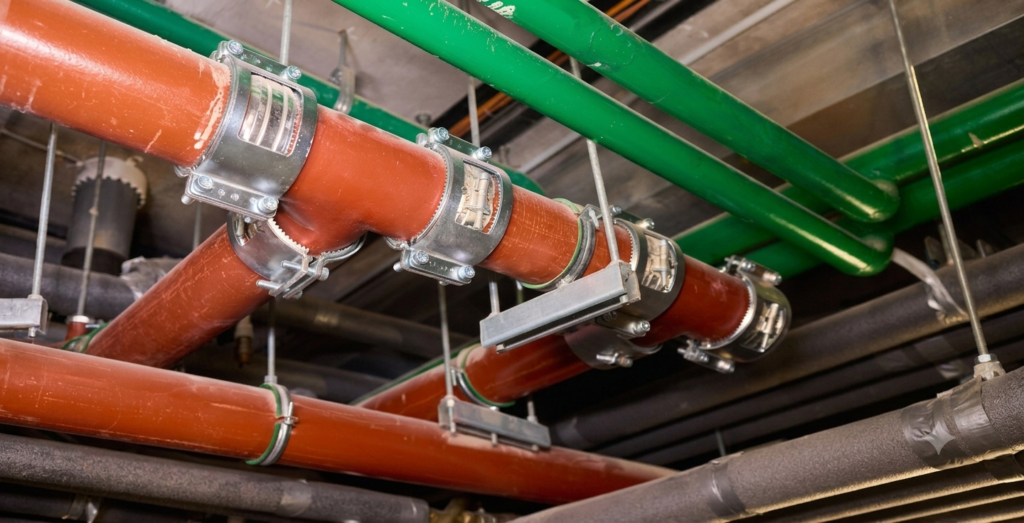
Quality assurance procedures require testing protocols prior to building occupancy. Domestic water distribution systems must undergo hydrostatic pressure testing—typically at 1.5 times the working operating pressure for a minimum of 2 hours—to verify joint integrity. Sanitary DWV networks require water pressure testing (filling stacks to a minimum 10-foot head of water) or air pressure testing (5 psi sustained for 15 minutes) to confirm air- and watertight performance before wall enclosures are installed. Domestic hot water systems must also undergo thermal disinfection commissioning to prevent Legionella growth and ensure safe system operation before occupancy. microbial contamination.
8. Strategic Conclusions and Engineering Implementation Framework for Plumbing Design Services
High-performance plumbing design services synthesize advanced fluid dynamics, regulatory compliance, multi-trade coordination, and digital asset management. By applying probabilistic sizing methodologies via Hunter’s curves, enforcing slope and velocity controls, and leveraging BIM coordination tools, engineering teams can minimize capital costs while ensuring long-term system reliability.
Adhering to ISO 19650 information governance, ISO 13567/AIA CAD layer standards, and structural clash resolution hierarchies prevents field rework and accelerates off-site prefabrication. Aligning plumbing systems with mechanical air handling networks and protecting electrical infrastructure ensures overall building safety and operational continuity. As sustainability standards emphasize water conservation, rainwater harvesting, and energy recovery, expert plumbing engineering remains critical to delivering resilient, high-efficiency infrastructure for the modern built environment







