

Articles

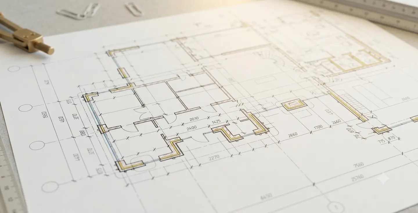
To build functional properties, advanced MEP Engineering Services operate as the core systems that transform static architectural drawings into dynamic, liveable, and highly efficient modern facilities. While structural engineering is fundamentally concerned with ensuring the physical frame can withstand gravitational, seismic, and wind loads, the disciplines of building services engineering focus on maintaining the internal conditions required for human occupancy, technological operations, and mechanical functionality. When modern projects undergo development or retrofitting, the mechanical, electrical, and plumbing systems collectively constitute up to half of the total capital cost, highlighting their importance in the project lifecycle. Navigating the division of responsibilities across these trades is a prerequisite for optimizing structural integration, streamlining municipal approvals, and managing operational energy expenditures.
Comparative Scope Analysis: How MEP Engineering Services Differ in Scope
Establishing the boundaries of each discipline requires looking closely at how they handle energy, mass, fluids, and spatial distribution within a building envelope. Though these systems share structural paths—such as floor penetrations, ceiling plenums, and utility risers—they are guided by distinct physics principles, calculations, and regulatory standards.
The Thermodynamic Mechanics of HVAC and Exhaust Systems
Mechanical engineering services focus primarily on managing thermodynamic and psychrometric conditions to maintain thermal comfort, indoor air quality (IAQ), and environmental stability. The scope of this trade covers the design of primary heating, ventilation, and air conditioning systems, along with active exhausting, air filtration, and mechanical pressurization systems.
At the center of mechanical design are detailed thermal load calculations that determine the heating and cooling capacities required for a building. These calculations assess several variables, including the thermal transmittance (U-values) of the envelope materials, solar heat gain coefficients through glazing, internal sensible and latent heat gains from occupants and equipment, and ventilation loads. Using thermal load modeling, engineers calculate the sensible cooling load (Qs) with the following equation:
Qs = 1.08 × CFM × ΔT
This allows them to determine the volumetric airflow rate in cubic feet per minute (CFM) required for each zone. Mechanical designers then translate these calculations into a physical layout by developing a detailed HVAC layout plan that maps the pathways of sheet-metal ductwork, coordinates diffusers and grilles, and details air terminal devices.
Thermodynamic Load Sizing
Heating and cooling load calculations for system capacity selection.
▼
Air Balancing & Psychrometrics
Airflow optimization, humidity control, and indoor environmental analysis.
▼
Supply/Return Air Systems
- Chillers & Boilers
- Hydronic Piping Loops
- Air Handling Units (AHUs)
Ventilation & Exhaust
- Make-up Air Units
- Specialized Hoods
- Smoke Control Systems
Beyond air distribution, the mechanical scope also manages large-scale central plants, including water-cooled chillers, cooling towers, boilers, and hydronic loop distribution networks. For high-performance facilities, this scope extends to specialized ventilation designs, such as smoke control and evacuation systems, cleanroom filtration systems, and laboratory exhaust hoods.
In critical environments like animal research labs, mechanical engineering demands precise pressure control and high ventilation rates, often requiring 10 to 20 air changes per hour to keep contaminants and odors contained. Mechanical engineers are also tasked with psychrometric design, ensuring that relative humidity is strictly controlled to prevent biological growth and protect building materials.
The Electromagnetic Infrastructure of Electrical Systems
Electrical engineering services design and manage the safe distribution of power, digital signals, control data, and artificial light throughout a facility. Operating as the building’s power grid, this discipline manages energy transport, system safety, and functional illumination. The scope is divided into high-to-medium voltage power distribution, low-voltage systems, and auxiliary communications infrastructure.
Power distribution design starts at the utility service connection. Electrical designers calculate the total connected and demand loads of the building to size the service entrance conductors, main switchboards, and distribution panelboards. To maintain safety, engineers calculate three-phase electrical power using the formula:
P = √3 × V × I × cos(θ)
Where:
P = Three-phase electrical power.
V = Line-to-line voltage.
I = Line current.
cos(θ) = Power factor.is the power factor. This calculation helps optimize circuit loading and balance the phases.
Additionally, engineers conduct short-circuit and coordination studies to ensure that overcurrent protection devices, such as circuit breakers and fuses, trip in a selective manner during electrical faults, confining outages to local circuits. Integrating specialized electrical engineering services is crucial for conducting arc flash hazard assessments, labeling equipment with protective boundary metrics, and specifying personal protective equipment standards to protect maintenance personnel.
Power Distribution
Electrical power supply, distribution networks, and load management.
▼
Safety & Protection Engineering
Electrical safety coordination, protection devices, and system reliability.
▼
Lighting & Egress Systems
- Photometric Modeling
- Emergency Egress Pathing
- Daylight-Harvesting Controls
Low-Voltage (ELV) Systems
- Telecommunications & IT
- Access Control & CCTV
- Integrated Fire Alarms
Lighting design also falls within the electrical scope. Electrical designers perform photometric modeling to optimize light distribution, minimize glare, and ensure compliance with strict lighting power density (LPD) limits.
Emergency power systems, including diesel generators and central uninterruptible power supply (UPS) batteries, are designed to support life-safety systems, egress lighting, and critical equipment during municipal outages.
The auxiliary scope of electrical engineering also covers Extra-Low Voltage (ELV) networks, which support data distribution, structural telecommunications, IP security cameras, access control interfaces, intercoms, public address systems, and integrated fire alarm systems.
The Fluid Dynamics and Hydraulic Networks of Plumbing Systems
Plumbing engineering services manage the flow of water, gases, and liquid wastes through highly regulated piping networks. While some view plumbing as simple pipe routing, the professional scope involves complex fluid dynamics, hydraulic pressure control, and strict health and safety protocols. The plumbing discipline is divided into domestic water supply, sanitary drainage, storm drainage, and specialized gas systems.
Potable water design begins by calculating the building’s peak demand using Water Supply Fixture Units (WSFUs). In high-rise buildings, municipal water main pressures are typically insufficient to reach the top floors, requiring plumbing engineers to design booster pump packages and pressure-reducing valve stations to maintain steady pressure. The hydraulic head loss in these piping systems is calculated using the Darcy-Weisbach equation:
hᶠ = f × L/D × v²/(2g)
Where:
hᶠ = Friction head loss.
f = Darcy friction factor.
L = Pipe length.
D = Internal pipe diameter.
v = Fluid velocity.
g = Acceleration due to gravity.
This allows engineers to balance pressure losses from pipe friction against the elevation head. Plumbing designers also specify domestic water heaters and recirculating loops to provide hot water efficiently and safely.
Hydraulic Distribution
Water supply networks, pressure management, and fluid distribution systems.
▼
Sanitary & Waste Management
Wastewater collection, drainage design, and environmental protection systems.
▼
Stormwater Systems
- Roof Drain Sizing
- Detention Systems
- Rainwater Harvesting
Specialized Piping
- Medical Air & Vacuum
- Grease Trap Management
- Gas & Fuel Delivery
For sanitary drainage, plumbing engineers design gravity-based piping networks using Drainage Fixture Units (DFUs) to size waste stacks, horizontal branches, and sanitary sewer connections. Vents are carefully sized and routed to control air pressure in the drainage system, preventing sewer gases from entering occupied spaces.
Stormwater design is also handled by plumbing engineers, who calculate peak rainfall rates using the Rational Method to size roof drains, collection basins, and retention systems.
In specialized buildings, the plumbing scope expands to include medical gases, chemical neutralizers for laboratory waste, grease interceptors for commercial kitchens, and propane or natural gas distribution lines.
| Parameter | Mechanical (HVAC) | Electrical | Plumbing |
| Primary System Objective | Regulate microclimate, psychrometrics, and indoor air quality. | Distribute electricity safely and provide functional illumination. | Manage potable water, storm runoff, and sewage systems. |
| Calculation Methods | Load calculations, CFM airflow sizing, duct friction analysis. | Short-circuit faults, load calculations, photometric modeling. | WSFUs, DFUs, friction losses, peak storm runoff flows. |
| Core Equipment Sized | Chillers, boilers, air handlers, fan coils, VAV terminals. | Main switchgear, transformers, generators, panelboards. | Booster pumps, water heaters, backflow preventers, grease traps. |
| Governing Standards | ASHRAE 90.1, ASHRAE 62.1, IMC, and UFC 3-410-01. | National Electrical Code (NEC/NFPA 70), IEEE, and NFPA 70E. | International Plumbing Code (IPC), Uniform Plumbing Code (UPC). |
| Spatial Requirements | Large horizontal spaces in ceilings and large mechanical rooms. | Vertical walls, dedicated electrical closets, floor pathways. | Vertical floor penetrations, wet wall cavities, underground trenching. |
Physical Intersections and Cross-Disciplinary Interdependence
While these three disciplines have distinct goals, they cannot operate in isolation during design or construction. Because these systems are physically close and share building pathways, changes in one discipline often create a cascade of design changes in the others.
MECHANICAL
HVAC, Chillers, Controls
Condensate & Makeup Water Connections
ELECTRICAL
Switchgear, Feeders,
Sensors & Gen-sets
Control
PLUMBING
Pumps, Heaters, Drainage,
Specialized Gas Systems
The Thermal and Electrical Interface
The mechanical-electrical relationship is characterized by a continuous exchange of energy and heat. HVAC equipment represents the single largest electrical load in most commercial and industrial buildings. Consequently, any adjustment to the mechanical equipment—such as choosing variable refrigerant flow systems over water-cooled chillers—will shift the total electrical load profile of the facility.
Electrical engineers rely on mechanical schedules to size feeders, circuit breakers, and main switchgear. Conversely, artificial lighting generates heat that contributes to internal thermal loads.
Additionally, mechanical dampers, variable air volume terminals, and control networks require dedicated electrical connections. The design of these power and control connections must be coordinated to ensure they are represented on both mechanical control schedules and electrical panel drawings.
The Fluid and Thermal Interface
Mechanical and plumbing systems overlap in hydronic and thermal transfers. Heavy HVAC equipment, such as water-cooled chillers and evaporative cooling towers, requires a continuous supply of makeup water to replace water lost to evaporation. Plumbing engineers must design water supply systems that can meet this demand under peak operating conditions.
In addition, mechanical cooling coils generate condensate as they dehumidify air. Plumbing designers must coordinate drainage paths to safely carry this wastewater to the building’s drain system, preventing indoor flooding or humidity damage.
In sustainable facilities, grey-water reclamation and rainwater harvesting networks can be connected to cooling towers, reducing the building’s overall water and energy footprint.
The Fluid and Electrical Interface
Plumbing systems depend heavily on electrical services to power motors, controllers, and heating elements. Equipment such as domestic water heaters, sewage ejector pumps, storm pumps, and booster systems require dedicated electrical circuits with appropriate overcurrent protection.
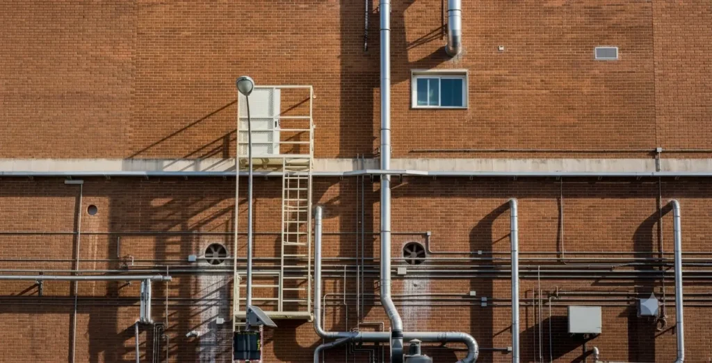
Because water and electricity pose a severe safety hazard when mixed, electrical engineers must specify ground-fault circuit interrupter (GFCI) protection and heavy-duty enclosures for installations in wet locations.
Plumbing piping must also be routed carefully to ensure it does not run above electrical switchboards, transform rooms, or server rooms, protecting critical electrical infrastructure from leaks.
| Interdependence Channel | Priming Action | Secondary Consequence | Required Interdisciplinary Coordination |
| Thermodynamic Heat Loads | Electrical lighting specified. | Internal sensible cooling loads increase. | Mechanical engineer updates cooling sizing. |
| Power Distribution Loading | Mechanical engineer selects HVAC equipment. | Electrical load profile of the facility changes. | Electrical engineer sizes panelboards and circuits. |
| Cooling Tower Evaporation | Air conditioners operated at peak capacity. | Make-up water consumption increases. | Plumbing engineer sizes main water supply connection. |
| Active Drainage | Air cooling coils produce condensation. | Wastewater must be safely drained. | Plumbing engineer designs gravity drainage path. |
| Hydraulic Pumping Power | High-rise pressure system specified. | High-load pumps require electrical power. | Electrical engineer runs power to wet zones. |
Digital Modeling and Automated Clash Detection in Unified Engineering Models
The design of modern building systems has evolved from traditional 2D drafting to detailed Building Information Modeling (BIM), which allows engineers to build a virtual representation of the facility before construction begins. Designers can prevent structural and system conflicts by using collaborative software like Autodesk Revit to model all building services in a shared 3D environment.
Using integrated MEP plan services is highly effective for coordinating complex installations. Automated clash detection tools analyze the 3D model to identify spatial conflicts between systems.
These conflicts are typically categorized as hard clashes—where two physical components occupy the same space, such as a wastewater pipe running through a structural beam—or soft clashes, where clearances required for code compliance, maintenance access, or thermal expansion are compromised. Resolving these issues in the digital model reduces field work, speeds up construction schedules, and minimizes expensive rework during installation.
Multi-Disciplinary 3D BIM Model
Integrated architectural, structural, mechanical, electrical, and plumbing models.
Navisworks / Revit Clash Engine
Automated model coordination, interference checking, and issue identification.
Hard Clashes
- Pipe through a beam
- Duct overlapping tray
Soft Clashes
- Blocked access panel
- Unsafe electrical clearance
BIM integration also streamlines material planning. Because components in a BIM model contain metadata such as dimensions, materials, and flow rates, estimators can generate accurate, automated quantity takeoffs (QTO). This automation helps the project team estimate material requirements, compare equipment configurations, and assess the financial impact of design modifications.
Additionally, structural design must coordinate with mechanical, electrical, and plumbing weights. For example, in laboratories and medical facilities, heavy air handling equipment can weigh thousands of pounds and generate high vibration loads. Structural engineers must design robust, vibration-dampening concrete slabs to prevent noise and structural fatigue across the building.
| Specialized Facility Type | Structural Challenge | Mechanical Requirement | Electrical Requirement | Plumbing Requirement |
| Animal Research Lab | Heavy live load, concrete slabs for vibration control. | 10 to 20 air changes per hour; strict relative humidity limits. | Reliable backup generators, weather-proof wet outlets. | Dedicated animal watering systems, wash-down drains. |
| Industrial Warehouse | Large open spans, minimal structural supports. | Sizable volume air heating/cooling, specialized exhaust. | High-load coordination for industrial machinery. | Stormwater control, grease traps, gas piping. |
| Commercial Data Center | Concentrated structural floor loads for server racks. | Precision cooling, liquid heat exchangers. | Dual-utility power feeds, generator backup, UPS systems. | Chilled water loops, clean-agent suppression systems. |
Contractual Frameworks and Project Deliverables
The delivery of mechanical, electrical, and plumbing engineering services is managed through specialized engineering contracts. These agreements establish the scope of work, coordinate design milestones, and assign operational liabilities among architects, engineers, and general contractors.
A detailed contract defines exactly what the design team will deliver. During the design phase, engineers produce permit-ready construction drawings, including mechanical air distribution layouts, electrical single-line diagrams, panel schedules, lighting levels, plumbing riser diagrams, and detailed calculations.
These documents are accompanied by written specifications that detail material standards, installation requirements, and equipment benchmarks to ensure compliance with building codes and facilitate the municipal permitting process.
[ Concept Phase ] ────> [ Engineering Calculations ] ────> [ Construction Documents ]
                                                                   │
                                                                   ▼
[ Facility Turn-over ] <─── [ Multi-System Commissioning ] <── [ Permit Approvals ]
Once construction is complete, the commissioning phase begins. The commissioning engineer is responsible for testing and validating that all systems function in accordance with the design specifications. This verification process includes balancing airflows, testing electrical trip settings, confirming emergency power transfer times, and checking pressure controls on backflow preventers.
Furthermore, because modern structures are designed to operate for decades, contracts often include provisions for ongoing preventative maintenance programs. These clauses require engineers to provide clear system manuals, outline schedule details for equipment checks, and define maintenance procedures. This thorough documentation helps facility managers avoid early system failures, minimize operational interruptions, and maximize equipment performance.
Regulatory Frameworks, Sustainability, and the Future of MEP
Designing modern building services requires adherence to complex local, national, and international safety codes. Because building codes exist to protect public safety and minimize resource consumption, engineers must design every component to comply with current municipal regulations.
In the United States, federal buildings are designed to meet performance-based requirements like the General Services Administration’s P100 standards, which emphasize energy efficiency, indoor environmental quality, and life-cycle cost analysis. Similarly, military facilities must comply with strict Unified Facilities Criteria (UFC), including UFC 3-410-01 for HVAC design and UFC 1-200-02 for sustainable building and water conservation.
Core Regulatory Standards
International codes and standards governing MEP design, safety, efficiency, and compliance.
ASHRAE 90.1 / 62.1
- Energy & IAQ Limits
- Fresh Air Requirements
- Ventilation Rates
NFPA 70 / NEC
- Power Distribution
- Safe Device Clearance
- Hazard Labeling
IPC / UPC Codes
- Sanitary Systems
- Water Conservation
- Pipe Sizing
At the same time, the industry’s focus has shifted toward high-performance, sustainable design. Modern mechanical services use advanced energy modeling and dynamic simulation software to optimize energy performance, reduce utility costs, and support green building certifications like LEED.
Electrical designers support sustainability by optimizing lighting power densities and designing smart building control networks that integrate daylight sensors and automated scheduling systems.
Plumbing designers support conservation by incorporating low-flow fixtures, waterless fixtures, grey-water systems, and rainwater harvesting infrastructure. Industry case studies—such as Patel’s empirical research in India—demonstrate that sustainable MEP engineering is no longer an optional feature, but rather an operational necessity for minimizing building lifecycle costs and reducing environmental impact.
Looking forward, the integration of smart technologies is reshaping how these services operate. The use of Internet of Things (IoT) sensors and smart devices allows facility managers to monitor energy usage, water flow rates, and indoor temperatures in real time. These cloud-connected control systems use artificial intelligence to automatically adjust ventilation, lighting levels, and heating cycles based on real-time occupancy and environmental conditions.
This shift is driving steady job growth in the sector; the U.S. Bureau of Labor Statistics projects employment of mechanical and electrical engineers to grow by 8% and 9% respectively, driven by urbanization and the demand for energy-efficient retrofits.
Systemic Conclusions and Actionable Synthesis
While mechanical, electrical, and plumbing systems manage different physical systems—thermodynamics, electromagnetism, and fluid mechanics respectively—they share the common goal of providing a safe, comfortable, and functional indoor environment. Designing these services as isolated components can result in spatial conflicts, oversized equipment, and increased installation and utility costs.
By using advanced Building Information Modeling (BIM) tools, engineers can coordinate physical and operational paths, perform accurate clash detection, and optimize system sizes before construction begins. Implementing an integrated design approach allows project managers to streamline municipal permitting, reduce construction timelines, improve energy performance, and ensure long-term structural viability.







