

Articles

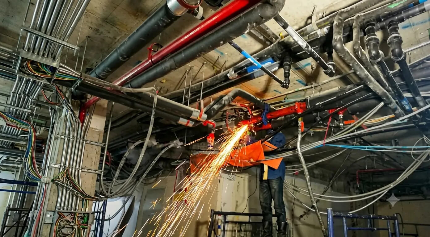
3D M and E coordination is transforming how architecture, engineering, and construction (AEC) professionals approach complex building services. In contemporary construction, modern buildings are far more than concrete structures and glass facades; they are highly intricate technological ecosystems. Within the walls, ceilings, and floors of commercial towers, healthcare facilities, and industrial plants lies a complex labyrinth of mechanical ductwork, electrical cable trays, plumbing pipes, fire protection systems, and structural framing. Ensuring that all these vital systems fit seamlessly into constrained spatial envelopes without clashing with one another or compromising architectural and structural integrity requires meticulous planning.
Historically, MEP (Mechanical, Electrical, and Plumbing) or M&E (Mechanical and Electrical) coordination was performed using two-dimensional overlay drawings on light tables or computer-aided design (CAD) screens. Designers stacked architectural, structural, and service plans on top of each other, attempting to mentally visualize spatial conflicts and elevations. Inevitably, many clashes went unnoticed until construction began on site, leading to costly field rework, project delays, material waste, and strained relationships between contractors and subcontractors.
Today, the adoption of Building Information Modeling (BIM) and advanced spatial coordination workflows has revolutionized the industry. This comprehensive guide explores every facet of 3D M and E coordination, its methodologies, tools, workflow stages, benefits, challenges, and future trajectories.
What Is M&E Coordination and Why Is 3D Essential?
To understand the mechanics of coordination, one must first define what M&E coordination entails. Mechanical and Electrical (M&E) coordination is the multi-disciplinary engineering process of integrating all building services—such as HVAC ducts, power conduits, lighting fixtures, domestic water pipes, drainage lines, sprinkler networks, and low-voltage telecommunication cabling—into a unified physical space within a structure.
Why is the transition to a three-dimensional environment essential?
Traditional 2D drawings represent three-dimensional space on flat sheets of paper or digital 2D planes. While a 2D floor plan shows horizontal alignment (X and Y coordinates), it fails to adequately communicate vertical elevations (Z coordinates) across different trade disciplines. For example, a duct shown on a mechanical drawing might appear to clear a structural beam in plan view, but when installed on site, its vertical depth may intersect directly with an electrical cable tray or a fire sprinkler main running at the same ceiling elevation.
By contrast, 3D M and E coordination utilizes intelligent, parametric 3D models where every building element possesses precise geometric data, material properties, and spatial coordinates. This eliminates ambiguity, allowing engineering teams to visualize, analyze, and resolve spatial conflicts in a virtual environment before a single brick is laid or pipe is cut on site.
Core Disciplines Involved in M&E Coordination
Successful coordination requires active collaboration among multiple engineering disciplines and trade contractors. Each discipline brings its own spatial requirements, code compliance mandates, and installation tolerances to the collaborative model.
1. Mechanical Engineering and HVAC Services
Mechanical services typically occupy the largest spatial footprint within a building’s ceiling plenums and service shafts.
- Ductwork Networks: Supply, return, exhaust, and outside air ducts require substantial cross-sectional clearance. Large rectangular or round ducts must be routed meticulously to maintain specified airflows without excessive pressure drops or sharp bends.
- Central Plant Equipment: Chillers, cooling towers, boilers, air handling units (AHUs), and variable air volume (VAV) boxes demand specific service clearances, vibration isolation pads, and structural support weight distribution.
2. Electrical and Extra-Low Voltage (ELV) Systems
Electrical systems distribute power and communication signals throughout the entire facility.
- Cable Trays and Conduits: Heavy power cable trays, lighting circuits, and emergency power distribution lines must run along designated overhead pathways. They require careful separation from plumbing lines to prevent potential electrical hazards in the event of a leak.
- Lighting and Fixture Integration: Recessed light fixtures, pendant lights, exit signs, and emergency egress lighting must coordinate cleanly with ceiling grids, diffusers, and smoke detectors.
- ELV and Security: Structured cabling, fire alarm wiring, CCTV cameras, access control panels, and building management system (BMS) sensors add another layer of conduits and junction boxes that must be accommodated in congested ceiling spaces.
3. Plumbing, Drainage, and Sanitary Services
Plumbing infrastructure relies heavily on gravity, dictating strict installation constraints.
- Gravity Drainage: Sanitary sewer and storm drainage pipes cannot make arbitrary sharp vertical turns upwards; they require precise downward slopes (e.g., 1% to 2% gradient) to ensure proper effluent flow. This makes plumbing drainage one of the most inflexible trades in ceiling coordination.
- Domestic Water and Gas Piping: Pressurized copper, PEX, or steel pipes for cold water, hot water, hot water return, and natural gas can navigate around obstacles more easily than drainage pipes, but they still require secure hanging brackets and thermal insulation thickness allowances.
4. Fire Protection and Suppression Systems
Life safety systems are governed by stringent regulatory codes such as NFPA standards.
- Sprinkler Mains and Branch Lines: Fire sprinkler pipes must provide uniform coverage across all floor areas. Sprinkler heads must be centered precisely within architectural ceiling tiles and kept clear of obstructions from large HVAC ducts or structural beams.
- Standpipes and Fire Pumps: High-rise buildings require dedicated vertical standpipes and high-pressure pump rooms that demand careful structural slab loading and spatial coordination.
5. Structural and Architectural Elements
While structural engineers and architects do not install M&E services, their components define the physical boundaries within which services must fit.
- Structural Framing: Concrete flat plates, post-tensioned slabs, steel beams, girders, columns, and shear walls limit the available headroom. Service penetrations through structural beams or foundation walls require rigorous structural engineering approval.
- Architectural Finishes: Suspended acoustic ceilings, drywall bulkheads, interior partitions, and raised access floors establish the finished aesthetic envelope, dictating what must remain hidden and what can be exposed.
The Evolution: From 2D Drafting to 3D BIM Coordination
The transition from traditional drafting methods to advanced digital modeling represents one of the most significant leaps in construction history.
The Limitations of 2D Overlay Methods
In the era of Computer-Aided Design (CAD), coordination meetings involved printing out architectural, structural, and MEP floor plans on large plotters and overlaying them on light tables. Coordinators used highlighter pens to mark intersecting lines, guessing whether a pipe elevation of +10′-6″ would clear a duct elevation of +10′-2″ underneath a concrete beam set at +11′-0″.
This method suffered from severe systemic flaws:
- Human error in interpreting multiple overlapping 2D drawings.
- Inability to visualize complex 3D intersections, diagonal bracing, or curved architectural features.
- Outdated drawing revisions leading to miscommunication between trades.
- Discovery of clashes on the construction site, resulting in costly change orders and project delays.
The Advent of 3D BIM and Federated Models
Building Information Modeling (BIM) changed this paradigm entirely. Instead of disconnected 2D drawings, project teams create intelligent 3D digital representations of the building.
In a modern 3D M and E coordination workflow, each discipline authoring team (Architect, Structural Engineer, Mechanical Contractor, Electrical Contractor, Plumbing Subcontractor) produces its own native 3D model (e.g., in Autodesk Revit or Tekla). These individual models are periodically merged into a single Federated Model using coordination aggregation software such as Autodesk Navisworks or Solibri.
The federated model aggregates all spatial data into one unified interface, allowing project managers, engineers, and trade foremen to navigate through the virtual building as if they were walking through the completed structure.
Detailed Step-by-Step 3D M and E Coordination Workflow
Executing a successful coordination process requires a structured, multi-phase methodology. Rushing into modeling without a clear protocol often leads to chaotic coordination loops.
Phase 1: BIM Execution Plan (BEP) and Standards Setup
Before any modeling begins, the project team establishes a BIM Execution Plan (BEP). This foundational document outlines:
- Software versions and interoperability formats (e.g., IFC – Industry Foundation Classes).
- Modeling Level of Development (LOD) standards—ranging from LOD 200 (conceptual design) to LOD 400 (fabrication and assembly level detail) and LOD 500 (as-built).
- Coordinate systems, shared project base points, and grid references to ensure all discipline models align perfectly when merged.
- Naming conventions, layer standards, and clash tolerance thresholds.
Phase 2: Model Authoring and Discipline Contributions
Once standards are established, each trade specialist develops their respective service model:
- The structural engineer models foundations, columns, beams, slabs, and walls.
- The architect models interior partitions, ceiling heights, doors, windows, and shaft enclosures.
- The mechanical engineer or contractor models AHUs, chillers, pipe networks, and ductwork routing.
- The electrical contractor models cable trays, main switchboards, conduit banks, and lighting fixture placements.
- The plumbing and fire protection contractors model sanitary lines, domestic water supplies, and sprinkler grids.
Phase 3: Automated Rule-Based Clash Detection
When the individual models are federated, the BIM coordinator runs automated clash detection tests using specialized software algorithms. Clashes are categorized into distinct types:
- Hard Clashes: Occur when two physical objects occupy the exact same 3D space (e.g., a chilled water pipe running straight through a structural concrete column or an electrical cable tray intersecting an HVAC duct).
- Soft / Clearance Clashes: Occur when an object violates the required operational, maintenance, or code clearance zone around another asset (e.g., failing to leave enough space to pull out a fan coil unit filter or failing to maintain required electrical clearances in front of a switchgear panel).
- Workflow / Sequence Clashes: Occur when objects do not physically intersect in the final state, but the sequence of installation makes one impossible to install after another (e.g., installing a large overhead duct before erecting the structural steel hanging supports above it).
Phase 4: Clash Analysis, Grouping, and Prioritization
Automated clash tests often generate thousands of individual clash reports. A skilled BIM coordinator reviews and filters these results to eliminate false positives and group related clashes.
Clashes are prioritized based on industry-standard hierarchy rules:
- Gravity-fed systems take precedence because their slope cannot be altered arbitrarily (e.g., large sanitary drainage and stormwater pipes).
- Structural elements and large architectural shafts are fixed boundaries that services must work around.
- Large mechanical ductwork comes next due to its large cross-sectional area and inflexible turning radii.
- High-pressure piping and electrical cable trays possess greater flexibility and can be jogged or routed around larger obstacles more easily.
Phase 5: BIM Coordination Meetings and Conflict Resolution
The core of the coordination process takes place in regular coordination workshops (virtual or in-person) attended by BIM coordinators, project engineers, and trade foremen.
During these sessions, participants review flagged clashes in real-time, negotiate spatial priority, and agree on routing adjustments. For instance, if a drainage pipe conflicts with a ventilation duct, the mechanical team might split a large rectangular duct into two smaller flat ducts (duct aspect ratio modification) to gain the necessary headroom without altering the drainage slope.
Phase 6: Model Sign-Off and Shop Drawing Extraction
Once all major and minor clashes are resolved and verified through re-testing, the federated model reaches a “Coordination Complete” milestone.
From this fully coordinated 3D model, trade contractors extract precise fabrication drawings, spool sheets, hanger location plans, and CNC cutting files. Prefabrication shops can then manufacture duct segments, pre-assemble pipe racks, and fabricate structural supports with millimeter precision, confident that everything will fit perfectly upon arrival at the construction site.
Key Software Tools Used in 3D M and E Coordination
The success of modern coordination relies heavily on robust software ecosystems designed for multi-disciplinary collaboration.
- Autodesk Revit: The industry-standard BIM authoring software used by architects, structural engineers, and MEP consultants to create intelligent, parametric 3D building components.
- Autodesk Navisworks (Manage / Simulate): The premier project review and clash detection software. Navisworks aggregates massive multi-format models (RVT, IFC, DWG, NWC), performs advanced clash matrix testing, links models to construction schedules (4D BIM), and tracks issue resolution workflows.
- Solibri Office / Model Checker: A powerful quality assurance tool used for advanced rule-based checking, code compliance verification, and deep spatial validation of BIM models.
- Trimble Connect / Tekla Structures: Widely used in structural steel and precast concrete detailing, offering seamless cloud-based collaboration for complex structural-MEP integration.
- BIM 360 / Autodesk Construction Cloud (ACC): Cloud platforms that enable real-time model sharing, issue tracking, and centralized Common Data Environments (CDE) for distributed project teams.
Benefits of 3D M and E Coordination
Investing time and resources into rigorous 3D M and E coordination yields massive return on investment (ROI) throughout the project lifecycle.
1. Elimination of Field Rework and Cost Overruns
Discovering a clash on-site during installation halts construction, requires emergency engineering redesigns, wastes purchased materials, and demands expensive labor to tear out and reinstall work. Resolving these conflicts virtually in the 3D coordination phase reduces costly change orders to a bare minimum.
2. Schedule Compression and Predictability
Construction delays caused by coordination conflicts ripple through project schedules. When MEP trades spend weeks arguing over who gets ceiling space, downstream finishes (drywall, painting, flooring) are delayed. Coordinated models enable prefabrication, allowing off-site manufacturing of complex pipe skids and duct assemblies while site excavation and concrete pours are still underway. Off-site prefabrication slashes on-site installation time significantly.
3. Enhanced Safety and Maintenance Access
Proper coordination ensures that building services are not only installed without physical clashes but are also accessible for future operations and maintenance. Technicians need adequate clearance to inspect valves, replace filters, service motors, and reset circuit breakers without hazard. Furthermore, organizing overhead work cleanly reduces physical congestion and safety hazards for workers on-site.
4. Improved Material Efficiency and Sustainability
Uncoordinated routing often results in unnecessarily long pipe runs, excessive bends, and over-sized equipment to overcome high pressure drops. 3D coordination allows engineers to optimize routing paths, minimize material lengths, reduce energy consumption associated with fluid and air friction, and support green building certifications such as LEED.
Common Challenges in 3D M and E Coordination
Despite its immense benefits, 3D M and E coordination is not without operational hurdles. Project teams must navigate several common challenges to achieve success.
1. Lack of Interoperability and Open Standards
Different trade subcontractors often use disparate software platforms (e.g., Revit, MagiCAD, AutoCAD MEP, Plant 3D). Translating proprietary file formats into neutral exchange formats like IFC (Industry Foundation Classes) can sometimes result in data loss, missing parameters, or corrupted geometries if data exchange protocols are not strictly defined in the BEP.
2. Poor Model Authoring Quality (“Garbage In, Garbage Out”)
A 3D model is only as good as the engineers who build it. If trade contractors submit models with generic placeholders, inaccurate dimensions, unassigned parameters, or missing connection fittings, automated clash detection becomes unreliable, producing thousands of false clashes that waste valuable coordination meeting time.
3. Late Engagement of Subcontractors
In traditional design-bid-build delivery models, trade subcontractors are often brought on board after the design phase is completed. This creates a disconnect because design engineers may model theoretical pathways that are impractical or uneconomical to fabricate and install in the real world. Optimal 3D M and E coordination requires early contractor involvement (ECI) or integrated project delivery (IPD) frameworks where trade specialists contribute to the model from the schematic design phase onward.
The Role of Professional Engineering Support
Navigating the complexities of multi-disciplinary spatial integration requires specialized expertise and rigorous quality control. Partnering with experienced engineering teams ensures that every technical nuance—from complex HVAC psychrometric calculations to stringent electrical load distribution and pipe sizing—is executed flawlessly. Organizations seeking expert support can leverage specialized professional services such as comprehensive MEP Plan Services or dedicated cooling system configurations like an HVAC Layout Plan to streamline project workflows. For broader engineering inquiries, exploring established hubs like EngrTeam provides valuable insight into industry best practices.
Future Trends in 3D M and E Coordination
The landscape of building services coordination continues to evolve rapidly, driven by technological innovations.
Artificial Intelligence and Automated Clash Resolution
Emerging AI-driven BIM tools are moving beyond passive clash detection. Next-generation algorithms can analyze spatial conflicts and automatically propose optimized routing solutions based on predefined engineering rules, cost parameters, and geometric constraints, dramatically reducing manual coordination time.
Generative Design and Parametric Optimization
Generative design software allows engineers to input boundary conditions, spatial requirements, and performance criteria. The computer then generates thousands of potential MEP routing options, allowing the design team to select the most efficient layout for energy consumption, material cost, and spatial economy.
Cloud-Based Real-Time Collaboration
The shift toward cloud-based Common Data Environments (CDE) like Autodesk platforms enables global multidisciplinary teams to work on the same federated model simultaneously. Changes made by a mechanical engineer in London are instantly visible to the electrical contractor in New York and the site superintendent in Dubai.
Augmented Reality (AR) and Mixed Reality (MR) on Site
The bridge between the virtual model and the physical job site is closing through AR and MR hardware (such as Microsoft HoloLens or specialized tablets). Site supervisors can walk through an uncompleted concrete shell wearing AR headsets that overlay the fully coordinated 3D M and E model directly onto their field of vision, instantly spotting discrepancies between design intent and physical installation before drywall is closed up.
Conclusion
3D M and E coordination has evolved from a luxury engineering exercise into an absolute operational necessity in modern construction. By replacing ambiguous 2D drawings with intelligent, federated 3D digital models, project stakeholders can proactively identify spatial conflicts, optimize material routing, streamline schedules, and eliminate costly field rework.
Whether constructing a high-rise commercial tower, a mission-critical data center, or an advanced healthcare facility, embracing rigorous 3D M and E coordination practices ensures that the mechanical, electrical, and plumbing systems function in perfect harmony—breathing safe, efficient, and sustainable life into the built environment.









