

Articles
Cool Calc Manual D: The Ultimate Guide to HVAC Duct Design and Sizing

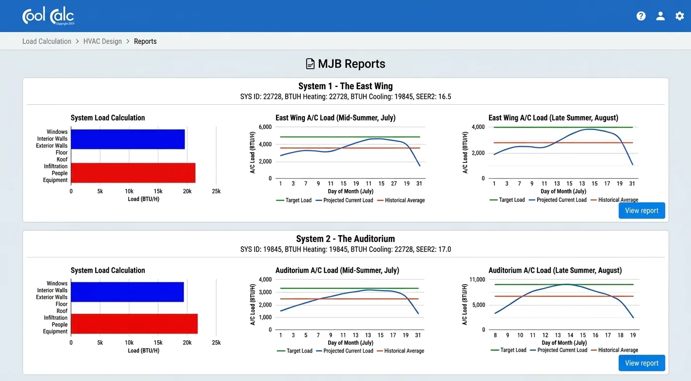
Cool calc manual d software solutions have transformed residential and commercial heating, ventilation, and air conditioning design by replacing tedious
Table of Contents
Cool calc manual d software solutions have transformed residential and commercial heating, ventilation, and air conditioning design by replacing tedious manual calculations with automated, ACCA-compliant workflows. In modern HVAC engineering, calculating heating and cooling loads via Manual J is only half the battle. Once the exact British Thermal Unit (BTU) requirements of a building are established, the conditioned air must be efficiently, quietly, and evenly distributed through a properly sized duct network. Without precise adherence to Air Conditioning Contractors of America (ACCA) standards, even the highest-efficiency furnace or air conditioner will underperform, resulting in hot spots, noisy airflow, excessive energy consumption, and premature equipment failure.
This comprehensive guide explores the principles of duct design, the mechanics of friction rate calculations, the transition from load calculation to duct layout, and how modern digital tools streamline the entire process for contractors and engineers.
1. Introduction to Manual D and Modern HVAC Design
For decades, duct sizing was treated as a rule-of-thumb exercise. Installers would run standard 6-inch flex ducts to every bedroom and 8-inch ducts to main living areas, ignoring actual static pressure drops, equivalent lengths, and airflow CFM (Cubic Feet per Minute) requirements. This outdated approach led to starved rooms, high static pressure, strained blower motors, and complaints from homeowners.
Manual D is the nationally recognized standard created by the Air Conditioning Contractors of America (ACCA) for residential duct systems. It provides the mathematical foundation and rigorous methodology required to design duct systems that deliver the correct airflow to every single room while maintaining proper external static pressure (ESP) across the HVAC equipment blower.
2. What Is Cool Calc Manual D and Why Is It Essential?
Cool Calc has emerged as an industry-leading web-based platform that simplifies load calculations and duct sizing. While many professionals are familiar with Cool Calc Manual J for load calculations, integrating cool calc manual d workflows bridges the gap between thermal loads and physical duct distribution.
Streamlining Complex Calculations
Traditionally, calculating friction rates, equivalent lengths for elbows, tees, transitions, and register boots required hours of looking up tabular data in bulky engineering manuals. Cool Calc Manual D automates these complex equations, allowing designers to input building geometry, equipment specifications, and layout configurations to generate accurate, code-compliant duct sizing reports instantly.
Ensuring Code Compliance and Permitting
Building departments across North America increasingly enforce strict energy codes (such as IECC and ASHRAE 90.1) that mandate proper Manual J, S, and D documentation for residential and light commercial building permits. Having a verified, automated calculation report prevents costly delays during municipal plan reviews.
3. The Foundations of ACCA Manual D Duct Design
To understand how software automation works under the hood, it is essential to review the core engineering principles governed by Manual D.
External Static Pressure (ESP) and Available Static Pressure (ASP)
Every HVAC air handler or furnace blower has a maximum external static pressure rating (typically around 0.5 inches of water column [in. w.c.] for standard residential split systems). The blower must overcome the resistance offered by:
-
Return air grilles and filters.
-
The indoor evaporator coil.
-
Supply and return duct trunk lines and branch runs.
-
Supply boots, diffusers, and registers.
Available Static Pressure (ASP) is the remaining pressure budget available specifically for the duct system after subtracting the pressure drops of the filter and evaporator coil.
Friction Rate ($FR$)
The friction rate represents the pressure drop per 100 feet of equivalent duct length, expressed in inches of water column per 100 feet ($in. w.c. / 100 ft$). The fundamental Manual D formula for calculating friction rate is:
$$FR = \frac{100 \times \text{ASP}}{\text{TEL}}$$
Where:
-
$FR$ = Friction rate ($in. w.c. / 100 ft$)
-
$ASP$ = Available static pressure ($in. w.c.$)
-
$TEL$ = Total Equivalent Length of the longest run (feet)
Accurately determining the Total Equivalent Length requires accounting for every fitting—such as elbows, wyes, transitions, and boots—by converting their geometric resistance into equivalent straight-pipe lengths using standard ACCA lookup tables.
4. Duct Materials and Friction Loss Characteristics
Different duct construction materials exhibit varying interior roughness coefficients, which directly impact airflow resistance and friction loss.
Sheet Metal (Galvanized Steel)
Rigid galvanized sheet metal ducts offer the smoothest interior surface, minimizing friction loss and maximizing airflow velocity. Properly sealed sheet metal ductwork is exceptionally durable, non-porous, and less prone to sagging or crushing.
Flexible Ducts (Flex Duct)
Flexible ducts consist of a wire helix core wrapped in plastic film and surrounded by fiberglass insulation. While flex duct is fast and inexpensive to install, it introduces significantly higher friction losses due to internal corrugations. Furthermore, if flex ducts are compressed, bent too sharply, or left sagging, their internal cross-sectional area decreases, causing severe airflow restriction. Cool Calc Manual D accounts for these installation imperfections by factoring in compression penalties during calculations.
5. Step-by-Step Workflow in Cool Calc Manual D
Executing a professional duct design project within an automated software environment follows a structured, sequential engineering workflow.
Step 1: Importing Manual J Load Data
The duct design process begins with a completed Manual J load calculation. Cool Calc allows designers to seamlessly link room-by-room heating and cooling loads, sensible/latent heat ratios, and required CFM airflow targets directly into the duct sizing module. Each room’s airflow requirement serves as the baseline target for sizing supply boots and branch ducts.
Step 2: Defining Equipment and Blower Performance
The designer inputs the selected HVAC equipment model (obtained from Manual S equipment matching). The software references manufacturer blower data curves to determine the exact blower performance at various static pressures, establishing the baseline ESP and airflow capacity.
Step 3: Laying Out Trunk Lines and Branch Runs
Using intuitive drawing interfaces, designers map out the spatial routing of supply and return trunk lines. Branch ducts are extended from trunks to individual room registers and grilles. The software tracks duct lengths, fitting counts, and terminal types across every zone.
Step 4: Automated Sizing and Balancing
Once the physical layout is completed, the software calculates the Total Equivalent Length (TEL) for every run, determines the critical run (the path with the highest resistance), calculates the allowable friction rate, and sizes every duct section (round, rectangular, or oval) to ensure balanced airflow delivery.
6. Key Benefits of Using Cool Calc Manual D
Adopting digital calculation tools delivers profound advantages for HVAC contractors, mechanical engineers, and property developers.
Elimination of Guesswork and Oversizing
Historically, contractors oversized ductwork and equipment to avoid callbacks for uncomfortable rooms. Oversized ducts lead to low air velocities, poor dust suspension, and stagnant air pockets, while oversized equipment short-cycles and fails to dehumidify properly. Precise calculation ensures optimal comfort and humidity control.
Reduced Installation Time and Labor Costs
With instant sizing reports and bill of materials generation, field technicians know exact duct diameters, takeoff sizes, and register locations before arriving on site, eliminating guesswork and reducing installation time.
Enhanced Indoor Air Quality (IAQ) and Comfort
Balanced airflow ensures that every room receives its precise volumetric share of conditioned air, eliminating temperature stratification between upper and lower levels, south-facing and north-facing rooms.
7. Common Duct Design Mistakes Prevented by Software
Even experienced installers occasionally commit design errors that compromise system performance. Automated tools prevent these pitfalls:
-
Excessive Flex Duct Lengths: Allowing long, snaking runs of flexible duct that increase static pressure beyond the blower’s capability.
-
Undersized Return Air Paths: Failing to provide adequate return air pathways (such as jumper ducts, transfer grilles, or dedicated returns in bedrooms), leading to positive pressure build-up and closed-door restriction.
-
Sharp Turns Near Registers: Placing elbows immediately before supply boots, which causes turbulence, whistling noise, and uneven air distribution across the diffuser face.
For comprehensive mechanical layouts and professional HVAC design support, explore specialized HVAC layout plan services.
8. Integration with Professional Engineering Services
While web-based calculators empower contractors to generate fast, accurate sizing reports, complex commercial buildings, multi-story residences, and custom architectural layouts often require multidisciplinary engineering oversight.
When coordinating complex building services—including structural penetrations, mechanical plant rooms, and centralized distribution risers—partnering with experienced engineering consultants ensures complete harmony between architectural form and mechanical function. To explore professional consulting packages, visit Engineer’s Team.
9. Conclusion
Mastering cool calc manual d workflows is essential for modern HVAC professionals committed to delivering high-performance, energy-efficient, and code-compliant heating and cooling systems. By bridging thermal load calculations with rigorous fluid dynamics and pressure loss principles, automated duct design eliminates guesswork, prevents equipment strain, and guarantees superior indoor comfort.
Whether designing a compact residential retrofit or a sprawling custom home, leveraging advanced calculation tools and professional engineering expertise ensures your duct systems operate at peak efficiency from day one.
Recent Posts
- Cool Calc Manual D: The Ultimate Guide to HVAC Duct Design and Sizing
- Understanding the Core Roles: Difference Between HVAC Designer and MEP Engineer
- 3D Modeling and Rendering Services in UK: The Ultimate Architectural Guide
- MEP Engineering Services for Healthcare: The Ultimate Guide to Clinical Facility Design
- MEP Engineering Consultants: The Ultimate Guide to Building Performance and Systems Integration