


Articles
Understanding Electrical Design Firms: Services, Process, and Selection Criteria
The modern built environment is a complex intersection of high-performance infrastructure, digital intelligence, and stringent safety protocols, placing electrical design
Table of Contents
The modern built environment is a complex intersection of high-performance infrastructure, digital intelligence, and stringent safety protocols, placing electrical design firms at the center of the construction and renovation lifecycle. As building systems evolve toward electrification, decarbonization, and smart integration, the role of the electrical engineer has expanded from a traditional focus on power distribution to the architecting of sophisticated energy ecosystems that support advanced mechanical systems and digital communication networks. This paradigm shift necessitates a granular understanding of the specialized services these firms provide, the rigorous processes they follow to ensure technical integrity, and the criteria by which professional peers and developers select them to mitigate risk and optimize capital expenditure.
The Technical Spectrum of Electrical Design Services
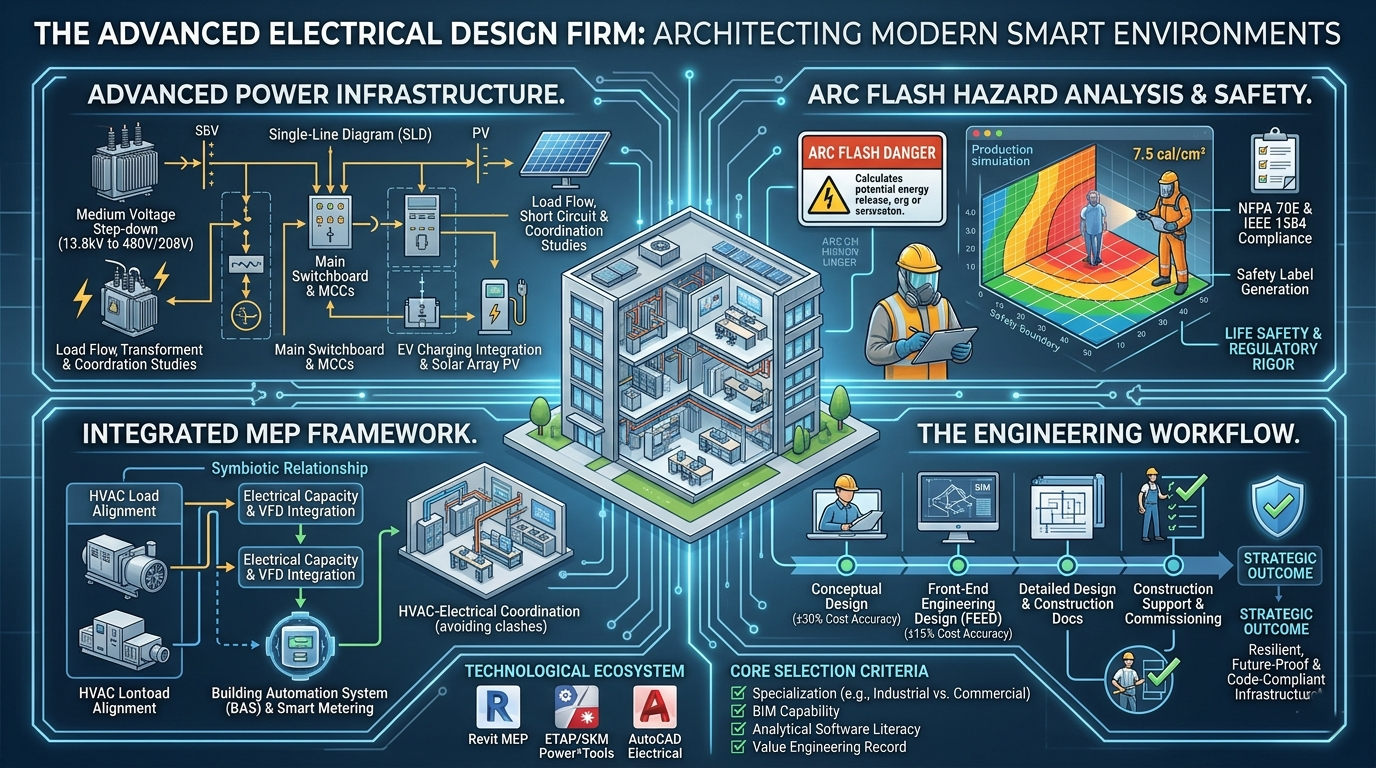
Electrical design firms operate across a multidisciplinary spectrum that bridges utility-scale energy delivery and localized point-of-use requirements. Their work begins at the service entrance, where high or medium voltage is stepped down through specialized transformers to meet the specific demand profiles of the facility. Expert firms demonstrate a nuanced understanding of these transitions, ensuring that the infrastructure is not only robust but also scalable for future technological advancements, such as the rapid proliferation of electric vehicle (EV) charging stations and building-integrated renewable energy sources.
Advanced Power Distribution and Infrastructure Engineering
At the core of an electrical design firm’s competency is the engineering of power distribution systems. This involves the systematic selection and placement of critical components including main switchboards, distribution panels, and motor control centers (MCCs). The engineering logic dictates that power must be distributed with minimal voltage drop and maximal efficiency, requiring precise calculations of conductor sizing and raceway capacity. For industrial facilities, this often encompasses medium-voltage design ($1kV$ to $35kV$), necessitating specialized expertise in protective relaying and insulation coordination.
The foundational document of this process is the Single-Line Diagram (SLD), which provides a comprehensive schematic representation of the entire electrical system. The SLD tracks the energy path from the utility transformer through every overcurrent protective device down to the individual branch circuits, serving as the primary roadmap for construction, maintenance, and future troubleshooting.
Specialized Technical Studies and Power Analysis
Design firms are increasingly tasked with performing complex analytical studies that ensure system reliability and personnel safety. These studies are conducted using sophisticated software engines and are often mandated by insurance providers and local building codes.
| Study Category | Technical Objective | Code Reference |
| Load Flow Analysis | Optimizes voltage levels and power factor across all nodes. | IEEE 399 |
| Short Circuit Study | Verifies equipment interrupting ratings against maximum fault current. | NEC 110.9, IEEE 141 |
| Coordination Study | Ensures selective tripping to isolate faults to the smallest possible zone. | IEEE 242 |
| Arc Flash Hazard Analysis | Calculates incident energy to determine safety boundaries and PPE requirements. | NFPA 70E, IEEE 1584 |
| Harmonic Analysis | Identifies distortions from non-linear loads like VFDs and LED drivers. | IEEE 519 |
Arc flash hazard analysis represents a critical intersection of engineering and workplace safety. By calculating the potential energy release during a fault, firms determine the appropriate Personal Protective Equipment (PPE) for electrical workers and generate safety labels for every piece of distribution equipment. These studies are living documents that must be updated whenever the system undergoes a significant modification, reflecting the firm’s commitment to the building’s operational lifecycle.
Lighting and Human-Centric Design Systems
Lighting design has evolved from a secondary aesthetic consideration into a data-driven discipline focused on energy optimization and occupant wellness. Expert firms utilize photometric software to model light levels in three dimensions, ensuring compliance with task-specific foot-candle requirements while minimizing light pollution and energy waste. Advanced lighting control systems—incorporating occupancy sensors, daylight harvesting, and tunable white light—are now standard in high-performance building designs, often integrating directly into the Building Automation System (BAS).
For developers, the aesthetic value of lighting is balanced with commercial viability. Firms must navigate the “BUG” rating system (Backlight, Uplight, and Glare) for outdoor fixtures to comply with dark-sky ordinances while enhancing the property’s security and curb appeal.
The Integrated MEP Framework: Synergy in Engineering
Modern electrical design is optimized only when it operates within a comprehensive MEP design environment. The interaction between electrical, mechanical, and plumbing systems is the primary driver of building performance, energy efficiency, and construction cost.
Electrical and HVAC Load Alignment
The mechanical system typically represents the largest electrical load in any commercial or industrial facility. Consequently, the electrical engineer’s work is deeply dependent on the HVAC layout design. Before a main switchboard can be sized, the mechanical team must complete its heating and cooling calculations, which determine the power requirements for chillers, boilers, air handling units (AHUs), and variable frequency drives (VFDs).
This relationship is inherently symbiotic. While the electrical system powers the HVAC equipment, the mechanical system must remove the heat generated by the electrical infrastructure itself, such as transformers, servers, and high-intensity lighting. Failure to coordinate these loads leads to “clashes” in the design—such as undersized cooling for a data center or insufficient electrical capacity for a rooftop chiller—resulting in expensive change orders during the construction phase.
Building Automation and Smart Integration
The convergence of these systems is managed through Building Automation Systems (BAS) and the Internet of Things (IoT). Electrical engineers design the low-voltage pathways and sensor networks that allow the mechanical system to respond dynamically to occupant behavior.
| System Component | Electrical Role | Integrated Outcome |
| Occupancy Sensors | Signals presence to lighting and HVAC. | Reduced energy waste in vacant zones. |
| VFD Integration | Powers and controls motor speeds. | Precise airflow control and energy savings. |
| Smart Metering | Monitors kWh consumption in real-time. | Data-driven energy management. |
| Fire Alarm Interface | Triggers AHU shutdown and smoke control. | Life safety and building code compliance. |
In this integrated model, the electrical firm acts as the provider of the building’s “nervous system,” ensuring that every mechanical component is not only powered but also intelligent.
The Engineering Workflow: Phases and Deliverables
The lifecycle of an electrical design project is a structured progression from high-level conceptualization to granular construction support. Each phase is defined by specific technical deliverables and levels of cost-estimation accuracy.
Phase 1: Conceptual and Schematic Design
During the conceptual phase (4-8 weeks), the design firm establishes the fundamental project parameters. Engineers perform preliminary load estimates based on square footage and building use, collaborating with architects to identify the location of electrical rooms and service entry points. At this stage, cost estimates are typically $\pm 30-40\%$ accurate, as they are based on block diagrams rather than specific equipment selections.
Phase 2: Front-End Engineering Design (FEED)
The FEED phase (3-6 months) is the most critical for cost control and system integrity. The firm develops a comprehensive load list, which may contain 500 to 2,000 line items, categorizing every piece of equipment and its operating characteristics. Key deliverables include definitive single-line diagrams, major equipment specifications (transformers, generators), and preliminary cable routing studies. This phase refines cost estimates to $\pm 15-20\%$ accuracy.
Phase 3: Detailed Design and Construction Documents
Detailed design (6-12 months) is the production of the “for construction” package. This involves the granular mapping of every conduit, cable tray, and wire in the building. Deliverables include:
- Cable Schedules: Detailed lists of every power and control cable, including conductor size and termination points.
- Panel Schedules: Specific circuit-by-circuit breakdowns for every distribution board.
- Site Layouts: Precise locations for receptacles, switches, and fixtures, coordinated with structural and mechanical drawings to prevent physical interferences.
Phase 4: Construction Support and Commissioning
The firm’s responsibility extends into the field through construction administration. This includes reviewing contractor submittals, answering Requests for Information (RFIs), and performing site observations to ensure the installation matches the design intent. During commissioning, engineers verify that the integrated systems—especially emergency power and fire alarms—operate correctly under fail-safe conditions.
Codes, Standards, and Regulatory Compliance
Electrical engineering is perhaps the most strictly regulated discipline in building design, governed by a hierarchy of safety codes and industry standards that dictate every aspect of the system.
The National Electrical Code (NEC/NFPA 70)
The NEC is the foundational standard for safe electrical installations in the United States. Revised every three years to incorporate new technologies like lithium-ion battery storage and bidirectional EV charging, the code sets the “minimum standard for safety”. While the NEC is not federal law, it is legally mandated by state and local governments, making compliance a prerequisite for building permits and occupancy.
The IEEE Standards and “Color Books”
While the NEC focus on installation, the Institute of Electrical and Electronics Engineers (IEEE) provides the “Color Books”—a series of recommended practices for the design and analysis of power systems.
| Book Color | Standard | Focus |
| Red Book | IEEE 141 | Industrial plant power distribution. |
| Green Book | IEEE 142 | Grounding of industrial and commercial systems. |
| Gray Book | IEEE 241 | Electrical systems in commercial buildings. |
| Buff Book | IEEE 242 | Protection and coordination of power systems. |
| Gold Book | IEEE 493 | Design of reliable power systems. |
| Emerald Book | IEEE 1100 | Powering sensitive electronic equipment. |
Firms also adhere to the National Electrical Safety Code (NESC) for utility-level infrastructure and NFPA 70E for electrical safety in the workplace.
The Technological Ecosystem: Software and BIM
The transition from 2D CAD to 3D Building Information Modeling (BIM) has fundamentally changed how electrical design firms collaborate with other trades.
Revit MEP vs. AutoCAD Electrical
- Revit MEP: This is a BIM authoring tool that creates a data-rich 3D model of the building. Every component in Revit contains technical information, allowing the software to automatically generate panel schedules, perform load totals, and—most importantly—conduct automated clash detection with mechanical ducts and structural beams.
- AutoCAD Electrical: While still used for 2D schematics and control diagrams, AutoCAD lacks the intelligent database of Revit. It is increasingly reserved for smaller projects or specialized industrial control panels where 3D coordination is less critical.
Power System Simulators
For engineering analysis, firms utilize specialized engines like ETAP, SKM Power*Tools, or EasyPower. These tools are designed to simulate the physics of the power system, calculating how the system will behave under fault conditions or peak demand. The integration of these analytical tools with the BIM model allows for a “Digital Twin” of the building’s electrical system, which can be used for real-time monitoring and predictive maintenance once the facility is operational.
Comparative Analysis of Load Requirements
Electrical design firms must tailor their approach based on the specific power profile of the facility type. The technical divide between residential, commercial, and industrial work is significant in terms of voltage, phase, and complexity.
| Feature | Residential | Commercial | Industrial |
| Service Voltage | 120/240V | 208/480V | Up to 13.8kV |
| Phase | Single-Phase | Three-Phase | Three-Phase |
| Service Amperage | 100A – 200A | 400A – 2000A+ | 2000A – 10,000A+ |
| System Load | 5kW – 12kW | 15kW – 300kW | 300kW – 50MW+ |
| Conduit Material | PVC, Romex | EMT, MC Cable | RMC, Heavy-duty Tray |
| Operating Hours | Peak: AM/PM | 8-12 hrs/day | 24/7 Continuous |
Industrial environments require significantly more robust protection systems due to the high available fault currents and the presence of heavy machinery that can cause power quality issues for sensitive electronics. Conversely, commercial design is often driven by energy codes and tenant-level metering requirements.
Selection Criteria and Professional Evaluation
Choosing the right electrical design firm is a risk-mitigation strategy for developers and project managers. Evaluation should focus on technical depth, software proficiency, and the ability to operate within an integrated MEP framework.
Core Evaluation Checklist
- Specialization: Does the firm have experience in the specific occupancy type? A residential specialist may struggle with the complex motor loads of a manufacturing plant.
- BIM Capability: Is the firm proficient in Revit MEP? On complex projects, firms that only offer 2D drafting often cause construction delays due to unresolved spatial clashes.
- Software Literacy: Does the firm own and actively use ETAP or SKM for power system studies? Ask to see a sample arc flash or coordination study to verify their analytical depth.
- Value Engineering Record: Can the firm provide examples where they optimized a design to save capital without sacrificing code compliance or reliability?.
- Regulatory Relationships: Does the firm have a positive history with the local utility (for service connections) and the AHJ (for permitting)?.
Interviewing the Firm: Key Questions
- “Describe your methodology for calculating demand factors for a mixed-use facility.” This tests their understanding of the NEC and their ability to avoid over-engineering.
- “How do you integrate renewable energy and storage into the main distribution system?” This evaluates their future-readiness for decarbonization trends.
- “What is your process for coordinating the electrical requirements of the mechanical system during the FEED phase?” This tests their collaborative MEP mindset.
- “How do you handle ‘selectivity’ in your coordination studies for critical facilities?” This ensures they understand how to prevent total building blackouts.
Economic Analysis: Costs and Timelines
The investment in a high-quality electrical design typically pays for itself through reduced construction rework and lower operational costs.
Fee Structures and Hours
Firms usually bill based on a percentage of construction cost, a fixed lump sum, or an hourly “Time and Materials” basis. For industrial projects, the FEED phase alone may require 1,500 to 4,000 engineering hours, costing between $\$225,000$ and $\$600,000$ depending on complexity. Detailed design, which involves specifying thousands of cables and conduit runs, can reach 4,000 to 12,000 hours for a mid-sized facility.
Timeline Benchmarks
- Schematic Design: 4-6 weeks.
- FEED Phase: 3-5 months.
- Detailed Engineering: 6-12 months.
- Construction Support: Ongoing for 12-24 months.
Utilizing a “Design-Build” model can accelerate these timelines by allowing construction teams to begin groundwork while engineers are still finalizing the branch circuiting.
Strategic Conclusion
The selection of an electrical design firm is a decision that impacts the safety, efficiency, and financial viability of a property for decades. As the global economy pivots toward total electrification, the “electrical” component of a building is no longer a utility service—it is a critical asset. By partnering with firms that demonstrate a deep mastery of integrated MEP design, maintain proficiency in 3D BIM modeling, and adhere to the rigorous standards of the IEEE and NEC, project stakeholders can build infrastructure that is not only code-compliant but also resilient and future-proof.
FAQs for Building Owners and Professionals
How can I ensure my building is ready for future technologies like EV charging or solar?
Future-proofing requires the design firm to build “spare capacity” into the main switchgear and provide dedicated conduit pathways to parking areas and rooftops. This initial investment is significantly cheaper than a full service upgrade five years later.
What happens if I skip the Arc Flash study?
Skipping the study is a violation of OSHA 1910 standards. In the event of an electrical injury, the owner faces severe legal liability and potential denial of insurance claims. Furthermore, workers may refuse to service energized equipment without the required labels.
What is the role of an electrical firm in LEED certification?
Electrical firms contribute to LEED through the design of energy-efficient lighting, high-efficiency transformers, and advanced metering that tracks performance. They provide the necessary documentation for the “Energy and Atmosphere” category.
How do I budget for the electrical portion of my project?
Initial budgeting should account for approximately $10-15\%$ of the total construction cost for electrical systems in commercial buildings, increasing for industrial or data-heavy facilities. Planning for high-quality engineering early (FEED) prevents the $30-40\%$ cost overruns common in under-designed projects.
What is the difference between a feeder and a branch circuit?
Feeders move large amounts of power from the main switchboard to distribution sub-panels. Branch circuits are the final stage of the system, moving power from the sub-panel to the individual lights, receptacles, and appliances.
- Tags: BIM, Electrical, HVAC, Technological Ecosystem
Recent Posts
- 5 Directives for Organizational Structure and Coordination in Engineering Teams
- What Are the Typical Pricing Models for MEP Engineering Consulting? A Comprehensive 2026 Industry Analysis
- Can You Recommend a Reliable MEP Engineering Service for Industrial Facilities?
- What are the top MEP engineering firms for commercial building projects?
- 10 Professional Development and Community Resources for Engineers in 2026
