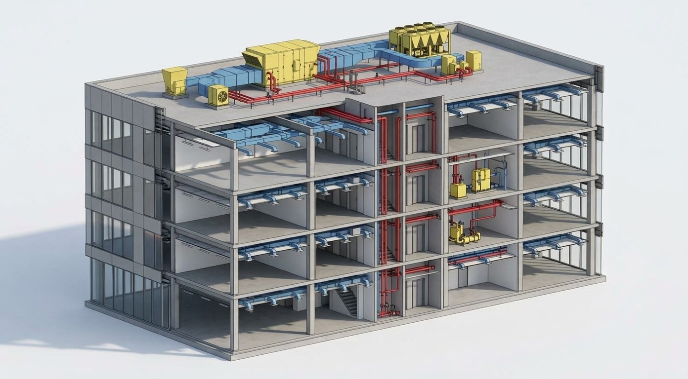
Core Components of Mechanical BIM Modeling
Mechanical BIM services span several detailed domains to cover the complete thermodynamic and airflow needs of a structure:
Ductwork Modeling: Precision routing of supply, return, exhaust, and fresh air ducts with accurate dimensions, dampers, fittings, insulation, and pressure drop attributes.Piping & Hydronic Systems: Comprehensive modeling of chilled water lines, hot water systems, refrigerant piping, condenser lines, and drainage systems.Equipment Placement: Intelligent positioning of mechanical components such as cooling towers, boilers, fan coil units (FCUs), variable air volume (VAV) boxes, and pumps.Thermal & Energy Analytics: Integration of spatial parameters to simulate heat loads, airflow patterns, energy efficiency, and environmental compliance.
The Strategic Importance of HVAC BIM Services in Modern Construction
Mechanical systems form the respiratory network of any building structure. In legacy workflows, mechanical coordination was handled through flat 2D overlays—a process prone to spatial conflicts, site delays, material waste, and spiraling budget overruns.
Implementing HVAC BIM services addresses these vulnerabilities by shifting error discovery from the construction field into a risk-free virtual environment.
Traditional 2D CAD Workflows Advanced HVAC BIM Workflows Static 2D drawing sheets with separate layer views Data-rich 3D parametric models with real-time sync Manual clash detection via transparent overlays Automated 3D clash detection across all disciplines On-site field adjustments and frequent change orders Off-site pre-fabrication and clash-free installation Manual quantity estimates prone to human error Automated, exact Bill of Quantities (BOQ/BOM) As-built drawings often disconnected from actual builds Digital twin delivery for life-cycle facility management
1. Eliminating Inter-Disciplinary Clashes
One of the greatest hazards in building construction is mechanical interference. A main supply duct routing through a structural steel beam or conflicting with plumbing risers can halt site operations for days.
With advanced 3D clash detection, specialized software checks the mechanical model against structural elements, plumbing lines, electrical trays, and architectural limits. Issues are resolved long before purchase orders are issued or fabrication starts.
2. Streamlining Pre-fabrication and Modular Construction
Pre-fabrication is revolutionizing construction efficiency. Because BIM models provide pinpoint geometric accuracy, mechanical contractors can pre-assemble duct spools, pipe racks, and equipment skids in controlled off-site manufacturing facilities.
These pre-assembled components are transported to the construction site and installed like modular modules, reducing site labor requirements, enhancing safety, and accelerating project timelines.
Detailed Breakdown of HVAC BIM Modeling Capabilities
To understand the full scope of mechanical BIM, it is helpful to look at the individual operational stages involved in delivering an end-to-end model.
01
Schematic Design & Load Calculations
02
Spatial Allocation & Duct Routing
03
High-Detail Parametric Modeling (LOD 100 – LOD 400)
04
Multi-Disciplinary Coordination & Clash Resolution
05
Fabrication Drawings & Spool Sheets
06
As-Built Modeling & Facility Management Delivery
1. Load Calculation and Airflow Simulation
Effective mechanical design begins with accurate load calculations. BIM-integrated tools calculate sensible and latent heat loads based on envelope insulation, window-to-wall ratios, solar orientation, geographical climate data, and internal occupant density.
Engineers can link these thermal calculations directly to air distribution networks, ensuring correct CFM (Cubic Feet per Minute) sizing across every room. To learn more about customized layouts and routing schedules, explore our dedicated HVAC layout plan
solution.
2. Ductwork and Piping Coordination
Routing large supply and return ducts through cramped plenum spaces demands smart spatial management. HVAC BIM services optimize duct paths to minimize pressure drops, reduce fan static energy usage, avoid friction losses, and preserve ceiling clearance requirements.
Similarly, hydronic piping systems are routed with accurate valve placement, insulation thickness clearances, expansion loops, and slope requirements to ensure smooth mechanical operation.
3. Equipment Modeling and Parametric Families
In BIM, equipment items are not mere graphical shapes—they are parametric objects loaded with manufacturer specifications, voltage, flow rates, weight, maintenance clearance buffers, and part model numbers.
Adding maintenance clearance buffers inside the 3D space ensures that technicians will have unhindered access to filter panels, valves, and control boxes after construction is complete.
Levels of Development (LOD) in HVAC BIM Projects
Building Information Modeling uses standardized Levels of Development (LOD) defined by the American Institute of Architects (AIA)
to specify the detail and accuracy of a model’s elements at various project milestones.
BIM Level of Development (LOD) Progression
LOD 500
As-Built Operations
LOD 100: Conceptual Model
The HVAC system is represented conceptually with generic spatial requirements, estimated overall building loads, and overall area footprints.
LOD 200: Schematic Design
Mechanical components are modeled as generic shapes with approximate size, shape, location, and orientation. Preliminary duct runs and equipment rooms are defined.
LOD 300: Detailed Engineering & Construction Documentation
Elements are modeled as specific assemblies with accurate dimensions, pathways, elevations, sizes, and connections. The model is fully coordinated against structural and architectural models for complete clash resolution.
LOD 400: Fabrication & Installation Modeling
The model includes fabrication-level detail. Duct spools are divided into shippable lengths with exact flange connections, hangers, stiffeners, damper mechanisms, and detailed assembly drawings ready for shop manufacturing.
LOD 500: As-Built & Facility Management
The final field-verified model accurately represents conditions as installed on site. Equipment attributes include warranty details, operation manuals, serial numbers, and maintenance schedules for long-term facility operation.
Key Benefits of Utilizing Professional HVAC BIM Services
Adopting integrated BIM workflows for mechanical systems delivers clear advantages to project owners, mechanical contractors, and consulting engineers alike.
Key Benefits of HVAC BIM
Lower Costs & Reduced Material Waste
Accelerated Construction Schedules
1. Significant Reduction in Request for Information (RFIs) and Change Orders
By resolving physical clashes, installation clearance bottlenecks, and routing errors virtually during the design phase, field-issued RFIs and costly emergency field modifications drop drastically.
2. Precise Material Quantities (BOQ / BOM Extraction)
Because BIM models store geometric and material metadata, accurate Bill of Quantities (BOQ) and Bill of Materials (BOM) can be generated automatically. This eliminates manual takeoff guesswork, avoids over-purchasing, and reduces material scrap on site.
3. Optimized Energy Efficiency & Sustainability Compliance
Integrated energy analysis helps design teams optimize thermal performance, select appropriately sized equipment, prevent system oversizing, reduce carbon footprints, and meet strict green building standards like LEED or BREEAM.
4. Improved On-Site Safety and Logistics
Fewer field adjustments mean less hot work, cutting, and grinding on elevated platforms. Pre-fabrication combined with precise installation sequencing improves overall site safety and keeps work sites clean and organized.
HVAC BIM Coordination Workflow Step-by-Step
A systematic coordination workflow ensures seamless integration across all project phases. The process generally moves through these distinct steps:
MEP Engineering & BIM Workflow
Step 1: Input Analysis
Architectural / Structural CAD / Scans
Step 2: Load Calculations & System Strategy
Thermal loads, sizing requirements, and distribution strategy
Step 3: 3D Modeling
Ductwork, Piping, Equipment layout and placement
Step 4: Automated Clash Detection & Resolution Meetings
Step 1: Input Verification and Protocol Setup
The engineering team collects architectural floor plans, structural models, site elevation data, and project execution standards (including naming standards, LOD targets, and coordinate origins).
Step 2: System Sizing and Mechanical Design
Engineers run heat load and ventilation calculations, establish duct velocities, select equipment, and layout primary mechanical distribution strategies.
Step 3: 3D Parametric BIM Development
Modelling specialists convert 2D mechanical concepts into data-driven 3D models within BIM platforms, building out duct routes, piping connections, and equipment placements.
Step 4: Multi-Discipline Clash Resolution
The mechanical BIM model is merged with structural, architectural, electrical, and plumbing models in a central coordination environment. Specialized software flags hard clashes (e.g., a duct intersecting a pipe) and soft clashes (e.g., insufficient access space in front of an electrical panel).
Step 5: Creation of Construction and Shop Drawings
Once the model is clash-free, automated 2D construction drawings, fabrication spools, duct hanger locations, and wall/slab penetration sleeves are extracted directly from the centralized model.
Step 6: As-Built Updates and Operations Delivery
During construction, any approved field modifications are recorded in the central model, delivering an accurate LOD 500 digital twin for lifecycle maintenance.
How HVAC BIM Services Support Facility Operations (COBie Integration)
The value of HVAC BIM services extends far beyond the construction phase. Once a building opens, facility managers face the task of keeping complex mechanical systems running efficiently.
BIM to Facility Management Lifecycle
3D Parametric Model
LOD 500 As-Built
COBie Data Extraction
Serial #s, Manuals
By linking BIM data with COBie (Construction-Operations Building Information Exchange) data standards, mechanical data transitions seamlessly into Computerized Maintenance Management Systems (CMMS) or Computer-Aided Facility Management (CAFM) platforms.
Key Lifecycle Advantages for Facility Managers:
Instant Asset Retrieval: Maintenance teams can locate hidden valves, dampers, and filters behind finished walls or ceilings using 3D spatial references.Streamlined Maintenance Schedules: Equipment models contain embedded maintenance manuals, warranty details, component replacement cycles, and service schedules.Predictive Diagnostics: Sensor data from Building Automation Systems (BAS) can be overlaid onto the digital twin to detect airflow anomalies, pressure drops, or equipment failures in real time.
Choosing the Right Partner for Mechanical BIM Services
Selecting an experienced engineering partner for HVAC BIM services ensures your project stays on schedule, under budget, and fully compliant with international building codes.
Key Capabilities to Evaluate in an MEP / BIM Partner
Expertise in International Building Codes (ASHRAE, SMACNA, IBC)
Multi-Discipline Integration (Seamless MEP-F Coordination)
Flexible LOD Support (From LOD 100 Concept to LOD 500 As-Built)
Proven Track Record in Clash Detection & Spatial Resolution
Working with specialized teams like EngrTeam
ensures that your mechanical, plumbing, and structural engineering needs are managed by experienced specialists committed to quality, accuracy, and efficiency.
Frequently Asked Questions About HVAC BIM Services
What is the difference between 2D CAD drafting and 3D HVAC BIM services?
Traditional 2D CAD provides flat vector drawings without embedded intelligence or dynamic updates. HVAC BIM services create parametric 3D models loaded with real physical and operational data. Changes made in one view automatically update all sections, schedules, and elevations, while automated clash detection identifies system conflicts long before construction begins.
How does HVAC BIM help lower overall project costs?
HVAC BIM reduces project costs by eliminating field rework, minimizing change orders, providing exact material takeoffs, and supporting pre-fabrication. Finding and fixing a clash in a virtual model costs a fraction of resolving that same issue on an active construction site.
What software platforms are typically used for HVAC BIM services?
Industry-standard software suites include Autodesk Revit, Navisworks for multi-disciplinary clash detection and coordination, AutoCAD MEP, Fabrication ESTmep/CAMduct for spooling and shop detailing, and BIM 360/Autodesk Construction Cloud for real-time cloud collaboration.
What Level of Detail (LOD) is required for mechanical fabrication drawings?
LOD 400 is required for fabrication and shop drawings. At LOD 400, models include exact manufacturer parts, precise duct connection flanges, hanger locations, stiffeners, sheet metal gauges, and complete spooling details ready for direct shop production.
Conclusion: Transform Your Mechanical Engineering Projects Today
Integrating comprehensive HVAC BIM services into your engineering workflow is essential for delivering modern, high-performance, cost-effective building projects. By combining precise 3D modeling, dynamic load analysis, automated clash detection, and pre-fabrication support, mechanical BIM eliminates spatial uncertainty and optimizes overall system performance.
Whether you are designing a high-rise office building, healthcare facility, or industrial site, partnering with experienced MEP specialists turns complex design challenges into efficient, constructible outcomes. Optimize your building designs today with expert engineering solutions tailored to your project requirements.