

Articles


In large-scale mep design for industrial facilities manufacturing plants, chemical processing units, distribution warehouses, and industrial complexes, operational continuity depends on high-capacity infrastructure. Engineering a heavy industrial building demands precision long before concrete is poured or machinery is anchored. Implementing professional mep design for industrial applications establishes the core mechanical, electrical, and plumbing infrastructure required to support continuous production cycles, satisfy strict safety mandates, and control lifetime energy costs.
Unlike standard commercial real estate, industrial environments face high thermal loads, hazardous airborne contaminants, significant motor startup currents, and complex process fluid requirements. Without structured engineering coordination, industrial sites risk unexpected downtime, severe cross-system physical clashes, and non-compliance with environmental or occupational safety laws.
Understanding MEP Design for Industrial Facilities
Industrial MEP engineering encompasses the specialized planning, sizing, and integration of mechanical HVAC and dust collection networks, high-voltage electrical distribution, process piping, and industrial wastewater drainage.
Industrial MEP System Integration
- Process HVAC
- Exhaust & IAQ
- Dust Capture
- High-Voltage
- Motor Control
- Backup Power
- Process Piping
- Trade Effluent
- Fire Networks
Where residential or light commercial planning focuses primarily on occupant comfort, industrial facilities prioritize process efficiency, continuous duty uptime, worker exposure limits, and heavy-duty load resilience.
Preventing Costly Spatial Clashes
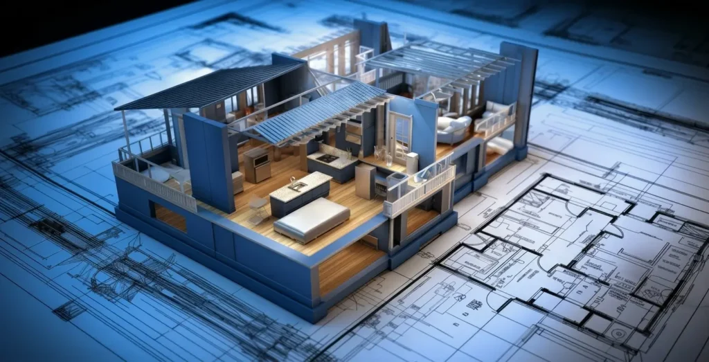
Industrial facilities contain dense collections of overhead infrastructure, including high-volume air ducting, cable trays, crane runways, steam lines, and fire suppression mains. Executing mep design for industrial facilities using 3D Building Information Modeling (BIM) allows engineers to run clash detection tests prior to procurement. Identifying physical interferences between heavy structural trusses and large-diameter process piping in a digital model eliminates costly field adjustments, rework, and project schedule delays.
Ensuring Compliance with Industrial Standards
Industrial MEP installations must adhere to stringent national and international regulatory frameworks. Mechanical ventilation must satisfy ASHRAE Standard 62.1 and OSHA ventilation thresholds to maintain safe indoor air quality. Electrical power distribution must comply with NFPA 70 (National Electrical Code) and IEEE guidelines, while fire suppression networks require strict alignment with NFPA standards. Adhering to these standards during initial design guarantees passing building inspections and operational licensing reviews.
Primary Components of Industrial MEP Systems
1. Mechanical Engineering (HVAC, Exhaust, and Climate Control)
Industrial mechanical systems regulate ambient factory temperatures, capture hazardous airborne particulates, and exhaust toxic fumes or waste heat generated by heavy manufacturing processes.
- Process Exhaust and Dust Collection: Tailored capture hoods, baghouses, cyclone separators, and scrubbers designed to pull combustible dust, solvent vapors, or welding fumes away from breathing zones.
- Make-Up Air Systems (MAU): Specialized supply air units engineered to replace heavy volumes of exhausted air, maintaining neutral atmospheric pressure inside the facility.
- Central Cooling and Heating Plants: High-capacity chillers, cooling towers, and industrial boilers supplying conditioned water or steam for plant processes and ambient space conditioning.
To discover how specialized airflow configurations prevent contamination and equipment overheating, review detailed HVAC Layout Plan Services built for complex operational environments.
2. Electrical Systems (Power Distribution and Automation)
Electrical design for industrial plants handles heavy utility incoming feeds, stepping down voltages safely to drive large industrial motors, automated conveyor systems, and high-intensity plant lighting.
- Substation and Switchgear Design: Step-down transformers, medium-to-low voltage switchgear, and Motor Control Centers (MCC) designed to distribute power across facility zones.
- Power Quality and Harmonics Mitigation: Integrating active harmonic filters, power factor correction capacitor banks, and transient surge suppression to safeguard sensitive programmable logic controllers (PLCs) from electrical noise.
- Uninterruptible Power Supply (UPS) & Emergency Generators: Redundant backup generators and industrial UPS batteries designed to keep critical production lines, safety controls, and fire pumps operating during main grid power outages.
Explore comprehensive load distribution, switchgear sizing, and power reliability strategies through targeted Electrical Engineering Services.
3. Plumbing and Process Piping
Industrial plumbing extends beyond typical domestic water supply and drainage; it manages high-pressure process gases, compressed air, chemicals, and industrial wastewater treatment.
- Compressed Air and Gas Piping: Engineered loops for compressed air, nitrogen, argon, or natural gas, optimized to minimize pressure drops and prevent fluid leaks.
- Industrial Wastewater and Effluent Treatment: Segregated drainage channels, oil-water separators, acid-neutralization basins, and trade effluent monitoring pits that process chemical waste before municipal discharge.
- High-Density Fire Suppression Systems: Deluge systems, pre-action sprinklers, and foam-water fire protection networks engineered to suppress high-hazard industrial fuel sources in compliance with NFPA Safety Standards.
Phase-by-Phase Process for Industrial MEP Engineering
Developing a robust mep design for industrial facility applications requires a methodical, multi-stage engineering workflow.
Phase 1: Operational Process Audit and Load Assessment
Engineers evaluate manufacturing flowcharts, machinery nameplate electrical ratings, process heat generation, exhaust CFM requirements, and plumbing utility consumption rates. Peak utility demand factors and concurrent load profiles are established.
Phase 2: System Architecture and Schematic Drafting
Engineers generate single-line electrical diagrams (SLDs), piping and instrumentation diagrams (P&ID), ductwork schematics, and plumbing riser diagrams. Utility equipment rooms, electrical vaults, and mechanical mezzanines are laid out.
Phase 3: 3D BIM Coordination and Spatial Optimization
Using digital modeling tools, mechanical ducts, heavy cable trays, and process piping are routed within the building structure. Spatial clearances around heavy machinery, maintenance access hatches, and overhead crane zones are verified.
Phase 4: Final Construction Documentation and Permitting
Comprehensive construction packages are finalized, including stamped engineering plans, equipment schedules, material specifications, sequence of operations (SOO) control narratives, and local authority permit submittals.
To access complete multidisciplinary engineering execution, review the unified MEP Plan Services provided by EngrTeam.
Key Formulas Applied in Industrial MEP Engineering
Industrial MEP design relies on physical and mathematical calculations to size systems correctly and avoid under- or over-engineering.
1. Industrial Fan Airflow Power Requirement (Mechanical)
Industrial MEP Engineering Formulas
To calculate the mechanical brake horsepower (BHP) required for an industrial exhaust fan moving contaminated process air:
BHP = (CFM × TP) / (6356 × η)
Where:
- CFM = Total Volumetric Airflow Rate (Cubic Feet per Minute)
- TP = Total System Static Pressure (Inches of Water Gauge – in. w.g.)
- η = Fan Static Efficiency (expressed as a decimal)
- 6356 = Standard Imperial Conversion Constant
2. Three-Phase Industrial Electrical Load Calculation (Electrical)
To determine total full-load current (Amperes) for three-phase industrial equipment:
I = (P × 1000) / (√3 × V × PF × η)
Where:
- I = Active Current (Amperes)
- P = Real Power Load (Kilowatts – kW)
- V = Line-to-Line System Voltage (Volts, e.g., 480 V)
- PF = Power Factor (typically 0.85 to 0.95 in industrial applications)
- η = Motor/Equipment Efficiency (expressed as a decimal)
3. Darcy-Weisbach Fluid Pressure Drop in Process Piping (Plumbing)
To estimate frictional head loss along an industrial fluid distribution line:
hf = f × (L / D) × (v² / 2g)
Where:
- hf = Head Loss due to Friction (Meters or Feet)
- f = Darcy Friction Factor (Dimensionless)
- L = Total Length of Pipe (Meters or Feet)
- D = Hydraulic Diameter of Pipe (Meters or Feet)
- v = Mean Fluid Velocity (Meters/Second or Feet/Second)
- g = Acceleration due to Gravity (9.81 m/s² or 32.2 ft/s²)
Comparing Conventional vs. Optimized Industrial MEP Systems
| Design Parameter | Conventional Field-Engineered Approach | Advanced Industrial MEP Design |
| Space Allocation | Uncoordinated trade routing causing field collisions | Pre-coordinated 3D BIM routing with zero field clashes |
| Power Distribution | Basic switchboards with high risk of voltage drops | Zone-based Motor Control Centers with power factor correction |
| HVAC & Exhaust | Generic constant volume ventilation | Variable air volume (VAV) & localized source capture filtration |
| Industrial Wastewater | Single direct drain to municipal lines | Neutralized, segregated trade effluent drainage networks |
| Maintenance Access | Difficult access around pipes and overhead ducting | Integrated maintenance clearances mapped into digital models |
Future Innovations in Industrial MEP Design
Digital Twins
& AI Sensing
Microgrids &
Battery Storage
Zero Liquid
Discharge
Digital Twins and AI-Driven Facility Management
Modern industrial complexes utilize live Digital Twins—virtual representations of the plant connected to IoT sensors monitoring air pressure, transformer temperatures, and pipe flow rates. AI algorithms analyze sensor data to execute predictive maintenance before mechanical bearings fail or piping scales up, preventing catastrophic manufacturing shut-downs.
On-Site Microgrids and Energy Storage
Industrial operations are increasingly deploying localized microgrids combining rooftop solar arrays, battery energy storage systems (BESS), and gas turbines. Advanced mep design for industrial plants coordinates these distributed energy resources to perform peak shaving—reducing electricity draw from the main utility grid during expensive peak-rate hours.
Zero Liquid Discharge (ZLD) and Water Recovery
With growing environmental regulations and water scarcity concerns, industrial plumbing designs are integrating Zero Liquid Discharge (ZLD) processing plants. Industrial wastewater is collected, filtered, evaporated, and purified within closed-loop systems, allowing facilities to reuse over 90% of process water while complying with strict local environmental discharge limits.
Overcoming Common Industrial MEP Challenges
Managing Extreme Heat Loads
High-temperature manufacturing processes (such as glass blowing, metal forging, or commercial baking) create extreme radiant heat. Standard ambient cooling units are insufficient. MEP engineers mitigate this by installing localized spot cooling, high-volume low-speed (HVLS) air circulation fans, and heat recovery exchangers that capture process exhaust heat to pre-heat domestic boiler water.
Mitigating Combustible Dust and Explosion Risks
Facilities handling wood, grain, plastics, or light metals generate fine combustible dusts. Standard electrical enclosures or improper exhaust ducting can trigger catastrophic explosions. Applying specialized mep design for industrial environments ensures all electrical equipment in hazardous areas uses explosion-proof (Class I, II, III Div 1/2) rated enclosures and spark-resistant ventilation ductwork compliant with NFPA guidelines.
Frequently Asked Questions (FAQ)
What is the main difference between commercial and industrial MEP design?
Commercial MEP design focuses on occupant thermal comfort, low operating noise, aesthetic ceiling integration, and standard utility distribution. Industrial MEP focuses on supporting heavy machinery loads, hazardous material ventilation, trade effluent treatment, continuous duty operations, and strict occupational safety compliance.
How does industrial MEP design reduce facility operating costs?
By sizing equipment accurately via precise load calculations, optimizing power factors to avoid utility penalties, implementing variable frequency drives (VFDs) on motors, and using waste heat recovery systems, engineered MEP plans significantly lower annual energy and maintenance expenses.
Why is 3D BIM clash detection critical for industrial projects?
Industrial plants contain dense concentrations of structural steel, heavy ducting, process piping, crane rails, and electrical cable trays. 3D BIM clash detection identifies physical overlaps between these components before on-site construction begins, eliminating expensive field modifications and project delays.
Conclusion
Executing a comprehensive mep design for industrial projects is essential for building a safe, high-performing, and resilient manufacturing facility. By systematically addressing mechanical process ventilation, high-voltage electrical distribution, process piping, and industrial fire protection during early design phases, engineers ensure smooth operations and long-term regulatory compliance. Partnering with experienced engineering professionals guarantees that your industrial plant operates at peak efficiency with minimal downtime and optimal energy performance.









