

Articles
HVAC Load Calculation Service: Comprehensive Engineering Principles, Building Physics, and System Optimization

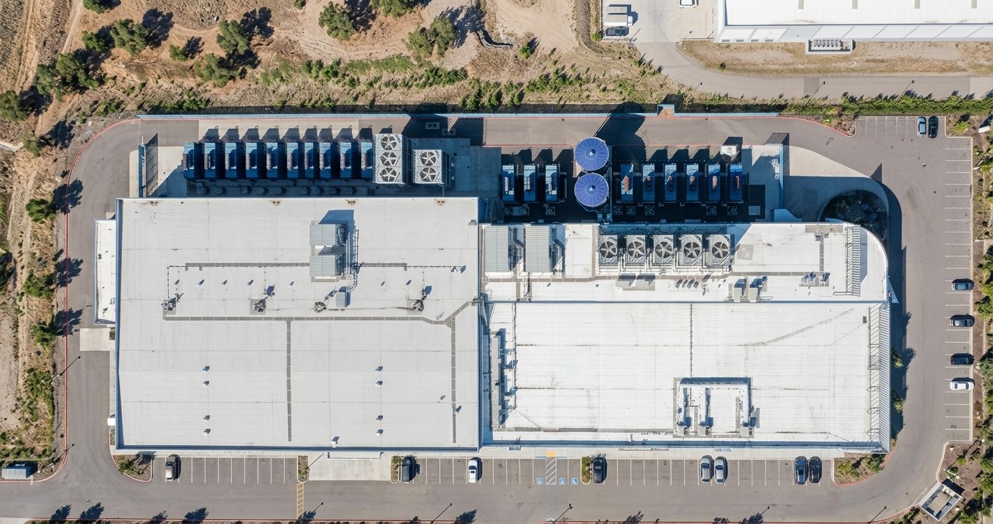
An expert hvac load calculation service provides the fundamental quantitative baseline required to engineer energy-efficient, resilient, and high-performing mechanical systems
Table of Contents
An expert hvac load calculation service provides the fundamental quantitative baseline required to engineer energy-efficient, resilient, and high-performing mechanical systems across residential, commercial, and industrial facilities. Heating, Ventilation, and Air Conditioning (HVAC) load calculations represent the rigorous scientific assessment of heat gain and heat loss within a structured space. Rather than relying on outdated rule-of-thumb estimations—which routinely result in oversized equipment, inflated capital expenditure, and compromised indoor environmental quality—modern engineering practices utilize dynamic thermodynamic modeling to quantify exact heating and cooling loads.
The ultimate objective of conducting a detailed thermal load calculation is to establish the precise volumetric airflow rates, refrigeration capacities, and heating inputs necessary to maintain indoor environmental design conditions during peak external weather events and internal operational surges. By integrating precise spatial parameters, building envelope thermal performance metrics, internal heat generation profiles, and psychrometric principles, mechanical design teams ensure optimal system sizing, prolonged equipment lifespan, and full alignment with regulatory energy standards.
Technical Foundation and Thermal Physics of an HVAC Load Calculation Service
The physical phenomena governing building thermal loads are rooted in classical thermodynamics and heat transfer mechanics, which are categorized into three primary modes: conduction, convection, and radiation. Thermal load calculations resolve the simultaneous heat flows occurring across the building envelope and within the internal volumes, separated into sensible heat gains (temperature changes) and latent heat gains (moisture addition).
Sensible Heat Exchange Mechanisms
Sensible heat transfer directly alters the dry-bulb temperature of the conditioned air. It is governed primarily by temperature differentials across assembly elements and internal energy dispatches.
Conduction through Building Envelope
Thermal transmission through solid assemblies such as exterior walls, roofs, slab foundations, and structural framing elements is modeled via Fourier’s Law of Thermal Conduction:
Q₍cond₎ = U × A × (T₍outdoor₎ − T₍indoor₎)
Where Q₍cond₎ represents the conductive heat transfer rate (Btu/h or Watts), U is the overall heat transfer coefficient (Btu/h·ft²·°F or W/m²·K), A is the surface area (ft² or m²), and T represents dry-bulb temperatures.
The overall thermal transmittance (U-factor) is the reciprocal of the total thermal resistance (R-value) of all material layers comprising the assembly, including air films and thermal bridges.
Solar Radiation through Fenestration
Radiant heat flux penetrating transparent or translucent surfaces, such as windows, curtain walls, and skylights, accounts for direct, diffuse, and ground-reflected solar radiation. This gain is modified by the Solar Heat Gain Coefficient (SHGC) and internal shading attenuation:
Q₍solar₎ = A₍fen₎ × E₍t₎ × SHGC × IAC
Where A₍fen₎ is the net glass area, E₍t₎ is the total incident solar radiation (Btu/h·ft²), SHGC is the solar heat gain coefficient of the fenestration system, and IAC is the interior shading attenuation coefficient.
Internal Sensible Gains
Sensible heat is released directly into the zone by occupants, lighting fixtures, information technology hardware, appliances, and industrial process machinery. Occupant sensible heat release varies according to metabolic work rates, ranging from sedentary office tasks to heavy physical labor. Lighting sensible gains are calculated based on installed electrical power modified by fixture usage factors and thermal storage factors.
Infiltration and Ventilation Sensible Load
Sensible energy is required to condition raw outdoor air introduced to the space intentionally through mechanical outdoor air dampers or unintentionally through envelope leakage. Sensible air load is calculated via standard air properties:
Q₍vent,s₎ = 1.08 × CFM × (T₍outdoor₎ − T₍indoor₎)
Where CFM represents the volumetric airflow rate in cubic feet per minute, and 1.08 is the volumetric heat capacity constant of air at standard temperature and pressure (0.075 lb/ft³ × 0.24 Btu/lb·°F × 60 min/hr).
Latent Heat Exchange Mechanisms
Latent heat gains involve the addition of moisture to the conditioned volume, requiring the HVAC system to perform phase-change work (condensation) at the cooling coil to maintain targeted indoor relative humidity levels, typically between 40% and 60% relative humidity.
Internal Latent Gains
Moisture is emitted into the air volume by human respiration and perspiration, cooking operations, open water features, process equipment, and indoor vegetation. The latent heat release from occupants increases proportionally with physical exertion and ambient dry-bulb temperature.
Infiltration and Ventilation Latent Load
Moisture mass is transferred from outdoor ambient air into the indoor space through outdoor air introduction. The latent heat burden of incoming air is expressed as:
Q₍vent,l₎ = 4840 × CFM × (W₍outdoor₎ − W₍indoor₎)
Where W represents the humidity ratio (pounds of water vapor per pound of dry air), and 4840 is the latent heat conversion multiplier (0.075 lb/ft³ × 1076 Btu/lb × 60 min/hr).
The total thermal cooling load imposed on the primary HVAC equipment is the scalar sum of the total sensible and latent loads across all conditioned zones:
Q₍total₎ = Q₍sensible₎ + Q₍latent₎ = 4.5 × CFM × (h₍outdoor₎ − h₍indoor₎)
Where h represents the enthalpy of the air stream (Btu/lb dry air), and 4.5 is the air density-mass flow multiplier.
Standardization Frameworks: ACCA Protocols and ASHRAE Methodologies
Formal thermal load calculations rely on standardized engineering methodologies to guarantee consistency, regulatory compliance, and system reliability. In North America and internationally, standards established by the Air Conditioning Contractors of America (ACCA) and the American Society of Heating, Refrigerating and Air-Conditioning Engineers (ASHRAE) form the structural backbone of load modeling software and manual procedures.
ACCA Protocol Suite (Manual J, N, S, and D)
The ACCA protocol suite defines distinct procedural standards tailored to building occupancy types and system design phases:
- ACCA Manual J (Residential Load Calculation): The recognized standard for sizing HVAC systems in single-family homes, multi-family units, and small low-rise residential structures. Manual J assesses thermal boundaries, fenestration orientation, local climate design conditions (99% winter dry-bulb, 1% summer dry-bulb), and duct heat gain/loss to establish room-by-room and total building loads.
- ACCA Manual N (Commercial Load Calculation): Tailored for commercial buildings, office complexes, retail centers, and institutional facilities. Manual N expands upon residential modeling by accounting for complex internal load schedules, occupancy diversity factors, multi-zone air distribution variations, high-density lighting arrays, variable occupancy patterns, and commercial kitchen or process exhaust requirements.
- ACCA Manual S (Equipment Selection): Utilizing the peak sensible and latent loads derived from Manual J or Manual N calculations, Manual S establishes criteria for selecting specific heating and cooling equipment. It prevents oversizing by restricting equipment selection based on total capacity limits (typically limiting sensible cooling capacity to 115% of total load and heat pump heating capacity to matched balance points).
- ACCA Manual D (Duct Design): Translates the zone-by-zone airflow requirements established during the load calculation process into detailed ductwork layout geometry, sizing trunk lines, branch runs, registers, and diffusers based on available external static pressure (ESP) and friction rates.
| Engineering Parameter | ACCA Manual J (Residential) | ACCA Manual N (Commercial) |
| Primary Building Focus | Single-family homes, duplexes, multi-family units | Office buildings, retail spaces, warehouses, institutions |
| Occupancy Profiling | Standard residential density (typical fixed count) | Dynamic diversity schedules, transient occupancy peaks |
| Ventilation Compliance | ASHRAE Standard 62.2 (Residential air exchange) | ASHRAE Standard 62.1 (Commercial outdoor air rates) |
| Internal Heat Densities | Low-to-moderate plug loads, residential lighting | High-density IT infrastructure, commercial lighting power densities |
| Duct System Thermal Losses | Evaluates unconditioned attic/crawlspace duct losses | Evaluates plenum spaces, return air paths, and chase losses |
| Diversity Factors | Rarely applied (coincident zone peaking assumed) | Routinely applied to reflect non-coincident peak loads across zones |
ASHRAE Dynamic Load Methodologies
For larger, highly engineered commercial structures, ASHRAE defines advanced dynamic load calculation methodologies that form the core calculation engines of modern building performance simulation software:
- Heat Balance Method (HBM): The most fundamental and rigorous calculation methodology. HBM simultaneously solves fundamental energy balance equations for every interior and exterior surface of the building enclosure, alongside an energy balance on the zone air volume. HBM accounts directly for inter-surface radiant exchange, conductive thermal mass delay, and convective heat transfer coefficients without empirical approximations.
- Radiant Time Series (RTS) Method: A simplified deterministic method derived directly from HBM. RTS replaces complex iterative matrix inversions with conduction transfer functions and radiant time factors. It isolates radiant heat gains from convective gains, delaying the radiant portion through time-delay series factors to simulate how building mass absorbs radiant energy and releases it as convective heat into the space air volume over time.
Mitigating Thermal Sizing Risks: Decarbonization, Efficiency, and System Performance
Executing a precise load calculation mitigates the operational, financial, and environmental risks associated with equipment mis-sizing. Historically, conservative design practices led engineers and contractors to apply excessive safety factors, yielding systems sized 30% to 100% above actual peak demand.
Thermodynamic Consequences of Oversizing
An oversized HVAC system cools the conditioned space rapidly, reaching the thermostat dry-bulb setpoint before completing an adequate operating cycle. This rapid shut-off—known as short-cycling—produces severe operational deficiencies across multiple operational domains:
- Dehumidification Deficit: Latent moisture removal requires continuous airflow over a cooling coil operating below the air dew-point temperature. Short-cycling prevents the coil from maintaining stable moisture condensation dynamics, leading to high relative humidity indoors, clammy conditions, and microbial growth.
- Mechanical Wear and Energy Inefficiency: Frequent starting cycles generate substantial electrical inrush currents, placing excessive thermal stress on motor windings, contactors, and scroll compressors. This reduces seasonal energy efficiency ratios (SEER2/IEER) and accelerates component failure.
- Elevated Capital Expenditure: Specifying oversized chillers, rooftop units (RTUs), or boilers increases initial capital costs for equipment, electrical infrastructure, structural supports, and piping distribution systems.
Thermodynamic Consequences of Undersizing
Conversely, undersizing an HVAC system prevents the facility from satisfying thermal setpoints during extreme outdoor design weather conditions. This results in persistent room temperature drift, occupant discomfort, continuous operation of auxiliary electric resistance heat in heat pump installations, and excessive utility costs.
Alignment with Net Zero, LEED, and Decarbonization Initiatives
As municipal codes mandate lower carbon footprints and absolute electrification, right-sizing HVAC systems through an accurate load calculation becomes a non-negotiable step in achieving green building certifications such as USGBC LEED, BREEAM, and Passive House. Heat pump technology performance, for example, is highly dependent on matching exact building thermal profiles. Proper load calculations allow engineers to select high-efficiency variable refrigerant flow (VRF) or hydronic heat pump systems that modulate seamlessly down to low turndown ratios without relying on carbon-intensive supplemental heating systems. To ensure long-term mechanical reliability and performance compliance, projects leverage comprehensive HVAC system design services built upon precise thermal load calculations.
Integrating Load Calculations with BIM and Multidisciplinary MEP Workflows
Modern building engineering integrates thermal calculations directly into Building Information Modeling (BIM) platforms, such as Autodesk Revit, enabling dynamic data exchange across architecture, structural engineering, and mechanical layout stages.
The BIM Data Pipeline for Thermal Modeling
The digital integration of load calculations follows a structured sequential pipeline:
- Architectural Space Modeling: The architectural model establishes spatial volumes, bounding elements, room geometry, orientation, and material assembly properties.
- Analytical Model Export: The BIM platform extracts building analytical models using green building XML (gbXML) or Industry Foundation Classes (IFC) protocols, transferring surface geometries and thermal boundary conditions to load calculation engines.
- Engine Computation: Specialized calculation engines (such as Carrier HAP, Trane TRACE 3D, or EnergyPlus) process hourly solar paths, internal loads, and thermal mass vectors to generate zone airflows and peak capacity requirements.
- Parameter Injection: Output metrics—including supply CFM, sensible/latent heat peak loads, fresh air minimums, and exhaust rates—are written back into the BIM room objects.
- Spatial Mechanical Design: Mechanical design engineers utilize populated room parameters to route ductwork, position air terminal units, size hydronic piping, and conduct clash detection across structural and electrical trades.
Level of Development Evolution in Load Calculations
The resolution of load calculations scales alongside the project’s Level of Development (LOD) throughout design and construction phases:
- LOD 100 / 200 (Conceptual & Schematic Design): Early-stage massing models provide rough surface-area-to-volume ratios. Load calculations rely on parametric building types to establish initial utility service entry sizes, plant room footprint requirements, and preliminary mechanical budget allocations.
- LOD 300 (Design Development): Architectural elements are fully defined with precise material layers and thermal properties. The BIM environment generates discrete thermal spaces and zones. Load engines calculate precise volumetric airflow rates , embedding these engineering attributes directly into the digital space parameters.
- LOD 400 / 500 (Fabrication, Construction & As-Built Operations): Mechanical equipment geometry, ductwork routing, terminal units, and piping distribution networks are modeled to exact fabrication dimensions for clash detection and off-site prefabrication. The calculated load metrics serve as the baseline verification standard during Testing, Adjusting, and Balancing (TAB) and post-occupancy commissioning.
| BIM LOD Level | Spatial Definition Quality | Load Calculation Functionality | Primary Mechanical Deliverable |
| LOD 100 | Conceptual massing geometry | Parametric volumetric load estimates | Preliminary mechanical room footprint |
| LOD 200 | Generic space boundaries & shells | Block load energy simulations | Equipment capacity estimates & riser paths |
| LOD 300 | Precise assembly layers & fenestration | Room-by-room peak & coincident loads | Fully sized terminal units, main ducts, hydronic mains |
| LOD 400 | Vendor-specific component geometry | Manufacturer equipment curve mapping | Fabrication spool drawings & pre-fab assemblies |
| LOD 500 | As-built field-verified installation | Operational digital twin baseline | Facilities management thermal monitoring model |
To ensure that mechanical load specifications seamlessly translate into physical, clash-free installation drawings, engineers deploy multidisciplinary MEP plan services that bind thermal calculations, electrical service sizing, and plumbing layouts into a unified spatial coordinate system governed by international standards such as ISO 19650.
Regulatory Compliance, Building Codes, and Jurisdictional Frameworks
HVAC thermal load calculations are strictly mandated by municipal, national, and international building codes to ensure minimum standards of energy performance and structural safety.
North American Building Codes
In Canada and the United States, compliance with energy standards is enforced through mandatory code adoption models:
- National Building Code of Canada (NBC): Published by the Canadian Board for Harmonized Construction Codes and the National Research Council, the NBC (including NBC 2020 and 2025 editions) sets technical provisions for structural, fire, and mechanical safety. Part 9 governs small housing and residential buildings up to three storeys, requiring explicit room-by-room load calculations based on prescriptive heat-loss and heat-gain limits. Part 6 governs complex mechanical systems in commercial structures, requiring rigorous engineering load calculations aligned with CAN/CSA standards and the National Energy Code of Canada for Buildings (NECB). Detailed building model codes and publications are maintained directly by the National Research Council of Canada.
- ASHRAE Standard 90.1 & International Energy Conservation Code (IECC): Enforced across US jurisdictions, these standards require that all mechanical heating and cooling equipment be sized in strict accordance with calculated loads. Sizing safety factors are strictly capped, forcing design teams to use real design weather data and audited building envelope performance metrics.
European and UK Frameworks
- UK Building Regulations (Part L): Mandates the verification of building carbon emission rates (BER) and target emission rates (TER) through dynamic thermal modeling. Mechanical load calculations must align with CIBSE Guide A parameters to verify comfort criteria and overheating risks.
- ISO 52000 Series: International standards governing the overall energy performance of buildings (EPB), establishing systematic calculation procedures for sensible, latent, and internal thermal loads across global climate zones.
Step-by-Step Engineering Execution of an HVAC Load Calculation
Executing an engineering-grade load calculation requires a structured, multi-phase operational workflow to capture every physical variable influencing thermal equilibrium within the space.
Phase 1: Building Envelope Audit
The design engineer conducts an audit of the building enclosure materials to calculate composite thermal transmittance values (U-factors):
- Opaque Assemblies: Determine layer-by-layer material densities, thicknesses, and thermal conductivities (λ-values) for exterior stud walls, mass masonry, exterior insulation finish systems (EIFS), concrete slabs, and roof assemblies. Account for thermal bridging caused by structural steel studs or concrete cantilever balconies.
- Fenestration Audit: Document overall assembly U-factors, center-of-glass values, frame thermal breaks, Solar Heat Gain Coefficients (SHGC), visible transmittance (VT), and internal/external shading geometry (overhangs, fins, deep reveals).
- Infiltration Rate Estimation: Quantify envelope tightness based on blower door test metrics (ACH₅₀) or empirical leakage tables, converting crack-length or surface-area leakage figures into design infiltration rates (CFM).
Phase 2: Design Weather and Site Conditions Selection
Extract statistical climatic data published in ASHRAE Fundamentals or regional meteorological databases:
- Winter Heating Design Condition: Select the 99.6% or 99% dry-bulb temperature condition (representing ambient temperatures equaled or exceeded during 99%+ of hours in a typical meteorological year). Solar heat gains and internal gains are conservatively set to zero during peak heating calculations to ensure safety under cold nighttime conditions.
- Summer Cooling Design Condition: Select the 1% or 0.4% summer dry-bulb temperature along with the mean coincident wet-bulb (MCWB) temperature to establish peak sensible solar and ambient conductive loads.
- Dehumidification Extreme Condition: Analyze peak dew-point temperature design conditions to evaluate maximum latent ventilation burdens.
Phase 3: Internal Heat Density and Diversity Scheduling
Catalog all internal thermal drivers acting within each thermal zone:
- Occupant Density & Activity: Assign metabolic heat generation rates (Btu/h per person) based on space function (e.g., seated office work: 245 sensible / 205 latent; heavy gym exercise: 525 sensible / 1025 latent).
- Lighting Power Density (LPD): Measure total installed lighting wattage per unit area (W/ft² or W/m²), accounting for LED ballast heat dissipation factors and control profiles.
- Plug Loads / Process Power: Inventory information technology racks, commercial kitchen equipment, laboratory hoods, and office electronics, applying diversity factors to reflect non-coincident peak operations.
Phase 4: Spatial Zoning and Airflow Psychrometrics
Divide the floor plan into discrete thermal zones based on solar orientation, exterior exposure, internal load profiles, and schedule profiles (e.g., perimeter office zones vs interior core zones vs high-occupancy conference rooms).
Utilizing psychrometric equations, map supply air conditions required to offset space sensible and latent loads:
- Occupant Density & Activity: Assign metabolic heat generation rates (Btu/h per person) based on space function (e.g., seated office work: 245 sensible / 205 latent; heavy gym exercise: 525 sensible / 1025 latent).
- Lighting Power Density (LPD): Measure total installed lighting wattage per unit area (W/ft² or W/m²), accounting for LED ballast heat dissipation factors and control profiles.
Lifecycle Economic Value and Asset Preservation
A detailed thermal load calculation provides clear financial benefits across the lifecycle of a facility, balancing initial capital investments with long-term operating costs.
Capital Expenditure Optimization (CapEx)
Right-sizing mechanical equipment directly reduces initial capital equipment costs. Oversized chillers, boilers, air handling units (AHUs), and pumps require larger electrical distribution panels, heavier structural roof curbs, increased pipe diameters, and expanded duct sizes. Eliminating redundant capacity frees up capital budgets for high-performance building envelope components, such as triple-pane glazing or continuous exterior insulation, which further reduces ongoing thermal loads.
Operational Expenditure Reduction (OpEx)
HVAC equipment operates at peak efficiency when operating near its continuous design rating. Variable speed drives (VSDs), inverter-driven scroll compressors, and modulating burner controls suffer efficiency penalties when throttled down to satisfy fractional loads caused by oversized design assumptions. Right-sized systems operate with longer, stable cycles, optimizing Seasonal Energy Efficiency Ratio (SEER2), Integrated Part Load Value (IPLV), and Annual Fuel Utilization Efficiency (AFUE) ratings.
Indoor Environmental Quality (IEQ) and Asset Preservation
Precision thermal load management prevents room temperature swings and maintains relative humidity within the recommended comfort zone (30% to 60% RH). Maintaining low humidity levels prevents condensation within exterior wall cavities, mitigating structural rot, metal stud corrosion, and mold growth. Furthermore, consistent thermal management improves human cognitive performance, reduces absenteeism, and protects sensitive equipment in data centers, laboratories, and manufacturing environments.
Engineering Synthesis and Implementation Guidelines
Establishing an accurate thermal load calculation is a necessary foundational step for modern building engineering. Moving away from crude area-based estimates toward rigorous thermodynamic modeling protects projects from structural, financial, and mechanical inefficiencies.
To achieve optimal building performance across residential, commercial, and industrial facilities, engineering teams and project stakeholders should implement the following core strategies:
- Deploy Advanced Physics-Based Calculation Engines: Utilize standard ASHRAE Heat Balance Method (HBM) or Radiant Time Series (RTS) tools—such as Carrier HAP, Trane TRACE 3D, or EnergyPlus—to capture complex solar, thermal mass, and schedule dynamics.
- Enforce Multi-Discipline BIM Integration: Ensure thermal load parameters are directly embedded into Building Information Models (BIM) to streamline downstream ductwork layout, hydronic pipe sizing, and inter-trade clash detection.
- Align Mechanical Sizing with Decarbonization Goals: Utilize precise peak and coincident load profiles to specify high-efficiency heat pumps, VRF systems, and heat recovery ventilation (HRV/ERV) units, advancing building decarbonization and compliance with international energy codes.
- Audit Envelope and Operational Inputs Thoroughly: Verify wall and roof assembly U-factors, fenestration SHGC values, blower-door infiltration metrics, and internal occupancy diversity schedules prior to finalizing equipment selections.
By grounding mechanical system design in thermodynamic principles, dynamic software simulations, and detailed building analytics, engineers, developers, and facility managers ensure that HVAC investments yield durable, energy-efficient, and comfortable indoor environments for the entire operational life of the facility.
- Tags: HVAC, Load Calculations
Recent Posts
- HVAC Load Calculation Service: The Ultimate Guide to Accurate Equipment Sizing and Energy Efficiency
- 3D M and E Coordination: The Ultimate Guide to Modern Building Services Integration
- What is a MEP Consultant?
- Engineering Calculation Services: The Backbone of Modern Design
- HVAC Drafting Services: The Comprehensive Guide for Modern Engineering









