

Articles
Manual J D S: The Complete HVAC Load, Duct, and Equipment Sizing Guide

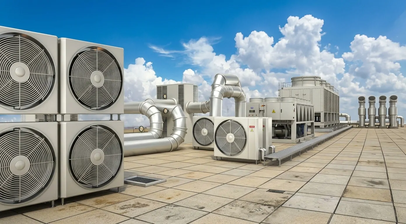
Manual J D S represents the three essential engineering standards published by the Air Conditioning Contractors of America (ACCA) for
Table of Contents
Manual J D S represents the three essential engineering standards published by the Air Conditioning Contractors of America (ACCA) for designing residential and light commercial HVAC systems. Without rigorous adherence to these protocols, contractors and builders frequently rely on outdated rules of thumb—such as sizing air conditioners strictly by square footage—which inevitably leads to short-cycling, uneven room temperatures, high humidity, excessive noise, and skyrocketing utility bills.
Mastering the sequential methodology of Manual J (Load Calculation), Manual D (Residential Duct Systems), and Manual S (Residential Equipment Selection) ensures optimal thermal comfort, superior indoor air quality, maximum energy efficiency, and strict compliance with modern building codes across North America.
1. Introduction to ACCA HVAC Design Standards
For decades, residential heating and cooling design suffered from guesswork. Builders and installers often sized HVAC units based on crude square-footage ratios (e.g., “one ton of cooling per 500 square feet”). While fast, this rule-of-thumb approach completely ignores modern advancements in building science, including high-performance spray-foam insulation, low-emissivity (Low-E) double- and triple-pane windows, continuous exterior air barriers, and regional solar heat gain variations.
When an HVAC system is oversized, it cools the air too rapidly and shuts off before removing ambient moisture, leaving the home feeling cold and clammy while subjecting the compressor to premature wear. Conversely, an undersized system runs continuously on peak summer or winter days without ever reaching the thermostat setpoint. To eliminate these costly design flaws, the industry relies on the integrated Manual J D S engineering framework—a scientific, three-step workflow that matches exact building thermal loads to precise equipment capacities and engineered air distribution networks.
2. Understanding the Manual J D S Workflow Sequence
Executing an HVAC design requires following a strict chronological order. You cannot size ductwork before knowing the required airflow, and you cannot determine airflow before knowing the exact capacity of the heating and cooling equipment.
+-------------------------------------------------------+
|  STEP 1: ACCA Manual J (Thermal Load Calculation)     |
|  - Calculates room-by-room heating & cooling BTUs     |
|  - Accounts for climate, windows, insulation, & leaks |
+-------------------------------------------------------+
                           |
                           v
+-------------------------------------------------------+
|  STEP 2: ACCA Manual S (Equipment Selection)          |
|  - Matches OEM performance data to Manual J loads     |
|  - Verifies sensible & latent cooling capacities      |
+-------------------------------------------------------+
                           |
                           v
+-------------------------------------------------------+
|  STEP 3: ACCA Manual D (Ductwork Sizing & Layout)     |
|  - Calculates friction rates & Total Effective Length |
|  - Sizes trunks & branches to deliver exact room CFM  |
+-------------------------------------------------------+
Each manual relies directly on the outputs of the preceding step. Skipping or abbreviating any stage invalidates the entire engineering calculation and compromises building performance.
3. Deep Dive into ACCA Manual J: Residential Load Calculation
ACCA Manual J is the gold-standard protocol for calculating how much heat a building loses in the winter and gains in the summer. Unlike simplistic square-footage estimates, Manual J evaluates every square foot of the building envelope and every internal heat source on a room-by-room basis.
Core Inputs Required for an Accurate Manual J Calculation
To produce a valid Manual J report, an HVAC engineer or energy modeler gathers detailed architectural and site data:
-
Local Climate Design Conditions: Outdoor winter heating design temperatures (99% dry bulb) and summer cooling design temperatures (1% dry bulb and coincident wet bulb), along with daily temperature range and elevation.
-
Building Orientation: The exact compass orientation of every exterior wall and window. West- and south-facing glazing receives intense afternoon solar radiation, dramatically increasing cooling loads compared to north-facing glass.
-
Thermal Envelope Properties: R-values for walls, ceilings, roofs, floors over unconditioned spaces, and slab edges.
-
Fenestration Metrics: U-factors (conductive heat transfer) and Solar Heat Gain Coefficients (SHGC) for every window, skylight, and glass door, plus exterior shading overhangs or interior blinds.
-
Air Infiltration Rates: Measured via Blower Door testing (ACH50) or estimated based on construction tightness classes (Tight, Semi-Tight, Average, Loose).
-
Internal Gains: Heat generated by occupants, kitchen appliances, lighting fixtures, electronics, and mechanical ventilation (ERV/HRV) fresh-air intake.
-
Ductwork Location & Leakage: Whether ducts run inside conditioned living space or through unconditioned attics and crawlspaces, which adds significant conductive and leakage loads.
Sensible vs. Latent Cooling Loads
Manual J separates summer cooling loads into two critical components:
-
Sensible Load: Dry heat that raises the air temperature (measured by a standard dry-bulb thermometer), driven by sunlight through windows, conduction through walls, and appliance heat.
-
Latent Load: Moisture in the air introduced through infiltration, occupant respiration, showering, cooking, and outdoor ventilation air.
Understanding the ratio between sensible and latent loads—known as the Sensible Heat Ratio (SHR)—is vital for selecting equipment capable of dehumidifying humid climates effectively.
4. Deep Dive into ACCA Manual S: Equipment Selection
Once Manual J establishes the exact heating and cooling loads (expressed in BTU/hr), ACCA Manual S governs how engineers select actual heating and cooling equipment from manufacturer performance tables.
Why Nominal Tonnage Is Misleading
A “3-ton” air conditioner is nominally rated at 36,000 BTU/hr under standard AHRI laboratory test conditions (95°F outdoor ambient, 80°F indoor dry bulb, 67°F indoor wet bulb). However, in the real world, if your home is located in Phoenix where outdoor temperatures hit 112°F, or in Miami where indoor wet-bulb conditions differ, that same 3-ton unit will deliver noticeably different sensible and latent capacities.
Manual S requires the engineer to look up the manufacturer’s Expanded Performance Data at the specific indoor and outdoor design temperatures established in Manual J.
Manual S Sizing Limits and Tolerances
ACCA Manual S enforces strict sizing boundaries to prevent oversizing:
-
Cooling Sizing Limits: For single-speed cooling equipment, total cooling capacity must generally fall between 95% and 115% of the Manual J total cooling load (or up to 125% for variable-speed inverter heat pumps and multi-stage systems). Furthermore, the equipment’s sensible capacity must meet the Manual J sensible load, and its latent capacity must meet or exceed the Manual J latent load.
-
Heating Sizing Limits: For gas furnaces, output capacity typically ranges between 100% and 140% of the Manual J heating load. For air-source heat pumps, sizing is primarily governed by the cooling load (within the 115%–125% ceiling), with electric auxiliary heat strips sized to cover the remaining heating deficit below the thermal balance point.
5. Deep Dive into ACCA Manual D: Residential Duct Design
After Manual J calculates room-by-room BTU loads and Manual S locks in the exact equipment model and total blower airflow (CFM), ACCA Manual D provides the fluid-dynamics methodology to size and route the air distribution system.
Calculating Room-by-Room Airflow (CFM)
Every room requires a specific volume of conditioned air, measured in Cubic Feet per Minute (CFM), proportional to its individual heating or cooling load. The fundamental sensible heat airflow formula is:
$$\text{CFM} = \frac{\text{Sensible BTU/hr}}{1.08 \times \Delta T}$$
Where $\Delta T$ represents the temperature difference between the supply air leaving the register and the room air (typically 18°F to 20°F in cooling mode). If a master bedroom has a large west-facing window requiring 4,200 BTU/hr of sensible cooling, Manual D ensures that exact CFM reaches the bedroom registers.
External Static Pressure (ESP) and Friction Rate
Air moving through ductwork encounters resistance, known as static pressure (measured in inches of water column, or in. w.c.). Every blower motor has a maximum rated External Static Pressure (commonly 0.50 in. w.c. for standard residential blowers).
Manual D walks the designer through a structured pressure budget:
-
Determine Available Static Pressure (ASP): Subtract the pressure drops of all internal and inline components—such as evaporator coils, air filters, electric heat strips, balancing dampers, and supply/return grilles—from the blower’s total ESP.
-
Calculate Total Effective Length (TEL): Identify the single longest duct run (supply plus return) from the air handler to the farthest register. Crucially, TEL is not just physical tape-measure distance; every elbow, wye branch, boot, and takeoff adds an Equivalent Length (EL) representing turbulence friction. A sharp 90-degree mitered elbow can add 30 to 60 feet of equivalent length!
-
Establish the Design Friction Rate: Divide the Available Static Pressure by the Total Effective Length and multiply by 100:
$$\text{Friction Rate} = \frac{\text{ASP} \times 100}{\text{TEL}}$$
With the friction rate calculated (typically falling between 0.06 and 0.18 in. w.c. per 100 feet), the designer uses a ductulator or software to size main trunk lines and individual branch runs while keeping air velocities below noise thresholds (generally under 700–900 FPM in trunks and 500–600 FPM in branches). For customized spatial routing and mechanical engineering drawings, explore our dedicated HVAC layout plan solutions.
6. How Manual T Complements the Manual J D S Triad
While Manual J, D, and S form the core engineering triad, professionals also integrate ACCA Manual T (Air Distribution Basics) to complete the design. Manual T governs the selection and placement of supply registers and return grilles.
Even if a Manual D calculation delivers the exact required CFM to a room, poor grille selection can ruin occupant comfort. If a supply register has insufficient “throw,” conditioned air drops prematurely without mixing across the room, creating hot or cold pockets. Conversely, excessive throw causes uncomfortable drafts or whistles against opposite walls. Manual T ensures proper air throw, spread, drop, and sound ratings (NC levels) for every diffuser and return grille in the building.
7. Regulatory Compliance, Energy Codes, and Permitting
In the United States and Canada, executing proper Manual J D S calculations is no longer optional—it is mandated by law in almost every jurisdiction.
IECC and IRC Code Mandates
Both the International Residential Code (IRC Section M1401.3) and the International Energy Conservation Code (IECC Section R403.7) explicitly require that heating and cooling equipment and ductwork be sized in accordance with ACCA Manual J, Manual S, and Manual D (or equivalent approved methodologies). Building inspectors routinely reject mechanical permit applications that lack stamped or verified ACCA load and duct reports.
Rebates, Tax Credits, and High-Performance Certifications
Federal energy efficiency tax incentives, utility heat-pump rebates, ENERGY STAR Certified Homes, and LEED for Homes programs all require documented Manual J D S submittals prior to installation. Industry standards maintained by organizations like the Air Conditioning Contractors of America (ACCA) serve as the legal benchmark for utility verification and code enforcement nationwide.
8. Common Mistakes and Pitfalls in Residential HVAC Sizing
Even experienced contractors occasionally stumble when transitioning from rules of thumb to true engineering calculations. Avoiding these frequent errors ensures superior system performance:
| Common Mistake | Engineering Consequence | Proper Manual J D S Solution |
| Using Block Loads Instead of Room-by-Room Loads | Total house tonnage may be right, but individual rooms become freezing cold or stiflingly hot. | Always run full room-by-room Manual J calculations to determine exact branch CFM. |
| Ignoring Dirty Filter & Wet Coil Pressure Drops | Underestimates static pressure, causing high friction rates and starved airflow at far registers. | Include realistic pressure drops for MERV 11–13 filters and wet evaporator coils in Manual D. |
| Using Flex Duct Without Accounting for Sag/Compression | Compressed or sagging flex duct doubles or triples friction loss, choking airflow. | Apply ACCA compression correction factors or specify rigid sheet-metal trunks with short flex runouts. |
| Oversizing Cooling for Extreme Heatwaves | Causes short-cycling during 98% of the summer, leading to mold, mildew, and high indoor humidity. | Stick strictly to the 99%/1% design weather tables and Manual S 115% capacity ceilings. |
| Undersizing Return Air Pathways | Creates negative building pressure, pulling humid attic/crawlspace air and backdrafting flues. | Design dedicated room returns or properly sized transfer grilles/jumper ducts per Manual D. |
9. Step-by-Step Guide to Implementing Manual J D S on a Project
Whether you are a custom home builder, architect, MEP engineer, or HVAC contractor, following a disciplined workflow streamlines permitting and installation:
-
Gather Architectural Plans & Specifications: Collect floor plans, elevations, window schedules (U-factor and SHGC), insulation specs, and target Blower Door infiltration rates.
-
Input Envelope & Zoning Data into Approved Software: Use ACCA-approved software tools (such as Wrightsoft Right-Suite Universal, Elite Rhvac, or Cool Calc) to build the thermal model room by room.
-
Review Load Outputs & Optimize Envelope Weaknesses: Identify rooms with disproportionate solar or conductive loads. Often, upgrading west-facing glass SHGC allows you to drop down half a ton in equipment size—saving thousands of dollars.
-
Select Equipment via OEM Expanded Data (Manual S): Match the heating/cooling loads against manufacturer performance matrices at local design temperatures, verifying sensible, latent, and total capacities.
-
Map the Ductwork Routing on Floor Plans (Manual D): Locate the air handler, identify structural joists/trusses, map trunk and branch paths, minimize sharp elbows, and compute Total Effective Length.
-
Generate Final Engineering Submittal Package: Compile the Manual J load summary, Manual S OEM performance sheets, Manual D duct sizing schedules, and CAD/BIM mechanical layout drawings for municipal permitting and field installation. For comprehensive multi-disciplinary engineering documentation, explore our MEP plan services or visit Engineer’s Team.
10. Conclusion
Delivering consistent indoor comfort, whisper-quiet operation, and peak energy efficiency requires abandoning outdated guesswork in favor of proven building science. The Manual J D S engineering framework—combining precise thermal load modeling, manufacturer-verified equipment selection, and fluid-dynamic duct design—eliminates short-cycling, humidity issues, and costly field callbacks.
By integrating ACCA Manual J, Manual S, and Manual D into your pre-construction workflow, builders, architects, and contractors ensure seamless permit approvals, code compliance, and long-term homeowner satisfaction.
- Tags: HVAC, hvac design, Manual JSD
Recent Posts
- Manual J D S: The Complete HVAC Load, Duct, and Equipment Sizing Guide
- Cool Calc Manual D: The Ultimate Guide to HVAC Duct Design and Sizing
- Understanding the Core Roles: Difference Between HVAC Designer and MEP Engineer
- 3D Modeling and Rendering Services in UK: The Ultimate Architectural Guide
- MEP Engineering Services for Healthcare: The Ultimate Guide to Clinical Facility Design