

Articles

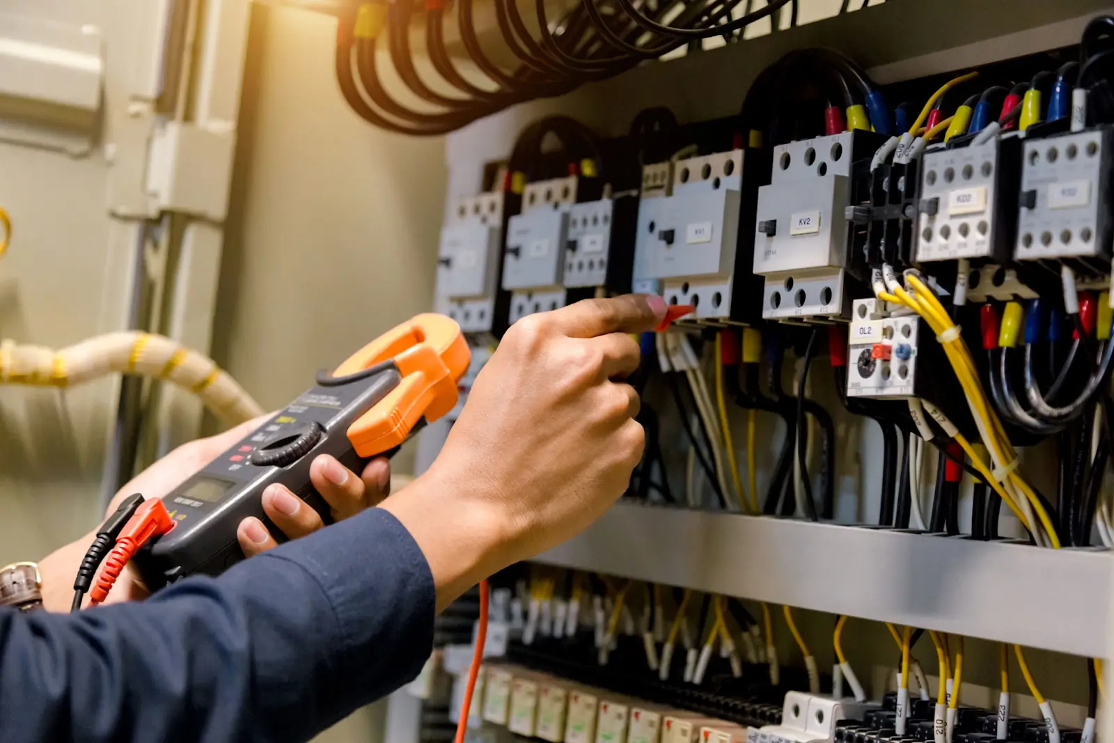
Professional mechanical room modeling services deliver the spatial precision and parametric intelligence necessary to transform crowded utility spaces into clash-free, constructible, and easily maintainable building environments. Mechanical rooms serve as the operational nerve center of modern commercial, industrial, institutional, and high-rise residential facilities. Within these tightly constrained mechanical basements, penthouses, and plant rooms, complex arrays of chillers, boilers, air handling units (AHUs), hydronic pumps, expansion tanks, heat exchangers, main electrical switchboards, and dense piping headers compete for finite spatial volume.
When utility designs rely on traditional 2D CAD overlays, hidden vertical interferences, inaccessible valve assemblies, and severe trade conflicts frequently remain unnoticed until physical installation begins. Implementing high-detail 3D Building Information Modeling (BIM) workflows for plant rooms addresses these challenges prior to field execution. By building a unified, data-rich digital twin during preconstruction, general contractors, engineering consultants, and trade sub-contractors can visualize complex assemblies, streamline prefabrication workflows, and ensure long-term operational safety.
Understanding the Core Purpose of Mechanical Room Modeling Services
Mechanical rooms house the central equipment responsible for heating, cooling, ventilation, sanitation, and power distribution throughout an entire structure. Because these spaces contain high equipment density, even minor misalignments in pipe elevation or duct routing can cascade into major construction delays, costly change orders, and compromised maintenance access.
The primary objective of mechanical room modeling services is to synthesize multi-disciplinary design requirements into a single, coordinated 3D parametric framework. Utilizing advanced software platforms such as Autodesk Revit MEP, Navisworks Manage, and AutoCAD MEP, mechanical room modeling bridges the gap between conceptual engineering schematics and real-world constructability.
Rather than treating mechanical, electrical, and plumbing (MEP) systems as isolated layers, 3D mechanical room modeling integrates every system component—including structural steel supports, wall penetrations, slab openings, and equipment clearance zones—into a shared virtual environment. As part of comprehensive MEP plan services, detailed plant room modeling ensures that every square inch of mechanical floor area is utilized efficiently and safely.
7 Major Benefits of Mechanical Room Modeling Services
Modern building projects demand strict adherence to construction schedules, tight budgets, and stringent energy efficiency standards. Engaging expert mechanical room modeling services delivers seven transformational advantages across the project lifecycle:
1. Early Spatial Conflict Resolution & Automated Clash Detection
In dense equipment rooms, physical clashes between trades represent one of the most significant sources of construction rework. Hard clashes occur when two physical objects occupy the same space (e.g., a heavy hydronic pipe intersecting a primary structural beam or an overhead duct). Soft clashes involve spatial clearance violations, such as placing a valve handle inside a wall or obstructing the pull space required to service a chiller barrel.
Through automated clash detection routines in Navisworks Manage, mechanical room modeling identifies spatial conflicts long before ground is broken. Engineers and BIM coordinators can run geometric rule checks, generate precise clash matrix reports, and resolve trade overlaps in digital space, eliminating reactive workarounds on the job site.
2. Optimizing Equipment Clearances and Maintenance Access Zones
A mechanical room must be designed for decades of ongoing operation, routine servicing, and major equipment replacement. If a pump, compressor, or control valve is rendered inaccessible by surrounding ductwork or electrical conduit, routine maintenance becomes labor-intensive and hazardous.
Dedicated mechanical room modeling embeds dynamic 3D clearance envelopes around key machinery. These clearance zones account for:
- Manufacturer service requirements: Coil pull spaces for Air Handling Units, tube pull zones for shell-and-tube heat exchangers, and filter replacement access.
- Code-mandated clearances: Working clearances around electrical panels and motor control centers (MCCs) as dictated by national electrical standards.
- Egress and walkways: Unobstructed primary walkways and egress routes for facility technicians carrying tools and replacement components.
3. Facilitating Off-Site Prefabrication and Modular Assemblies
Off-site prefabrication significantly accelerates construction timelines while raising installation quality and worker safety. Advanced mechanical room modeling allows engineers to elevate model fidelity to Level of Development (LOD) 400.
At LOD 400, every pipe spool, flange, fitting, hanger, drop-out section, and valve tag is modeled with exact dimensional accuracy. From these high-fidelity models, automated spool drawings, bill of materials (BOM), and cut sheets can be exported directly to off-site fabrication shops. Multi-trade mechanical skids—incorporating pumps, heat exchangers, expansion tanks, and control manifolds on a unified structural frame—can be manufactured off-site under controlled factory conditions, shipped to the job site, and hoisted directly into position.
4. Streamlining Multi-Disciplinary MEP Integration
Mechanical room design cannot exist in a vacuum; it requires continuous synergy between mechanical, electrical, plumbing, and structural disciplines.
- Integrated mechanical room workflows incorporate a fully coordinated HVAC layout plan to govern supply/return air ducts, exhaust fans, and chilled water loops.
- Simultaneous coordination with robust electrical engineering services guarantees that cable trays, busways, variable frequency drives (VFDs), transformer pads, and main distribution panels receive adequate space, dedicated containment, and safe clearance from liquid piping lines.
This integrated approach prevents trade collisions and fosters seamless collaboration between mechanical contractors, electricians, and plumbers.
5. Precise Material Take-Offs (MTO) and Cost Control
Budget overruns in MEP construction frequently stem from inaccurate material estimates or excessive field scrap. Parametric 3D mechanical room models maintain live database links to every component in the virtual building.
As the model evolves, automated schedules extract precise material take-offs (MTO), including total pipe lengths by diameter and material schedule, quantity of elbows and tees, valve counts, ductwork surface area, insulation volumes, and hanger counts. Accurate quantitative data enables preconstruction estimating teams to order exact material quantities, negotiate bulk procurement pricing, and minimize job site material waste.
6. Enhanced 4D Construction Sequencing & Temporal Logistics
Large mechanical room equipment—such as 500-ton centrifugal chillers, steam boilers, or custom AHUs—must often be rigged into position before structural walls or floor slabs above are poured.
By linking the 3D mechanical room model to the master project schedule (creating a 4D BIM simulation), construction managers can visually rehearse equipment rigging sequences. 4D modeling validates the critical path, identifies potential logistical bottlenecks, ensures temporal clearance for crane lifts and path-of-travel routes, and prevents trade-stacking within tight plant rooms.
7. High-Fidelity As-Built Models for Facilities Management (LOD 500)
Upon construction completion, the coordinated 3D mechanical room model is updated with field-verified changes to create an accurate LOD 500 As-Built digital twin.
This model serves as a valuable asset for building owners and facility management teams. Embedded within the model components are serial numbers, operation and maintenance (O&M) manuals, warranty expiration dates, maintenance schedules, and submittal documents. Integrating this BIM data with Computerized Maintenance Management Systems (CMMS) or Building Management Systems (BMS) allows operators to visualize system performance, execute predictive maintenance, and instantly trace piping routes behind walls or above ceilings.
Key Building Systems Integrated by Mechanical Room Modeling Services
A fully coordinated 3D mechanical room model incorporates a dense ecosystem of interconnected mechanical, hydronic, electrical, and control systems.
- Chilled Water
- Heating Water
- Condenser Water
- Pumps & Boilers
- Supply / Return Air Ducts
- Exhaust Risers
- Sound Attenuators
- Domestic Hot / Cold Water
- Backflow Preventers
- Sump Pumps
- Main Switchboards
- VFD Units
- Motor Control Centers (MCC)
- DDC Panels
- Sensor Wiring
- Control Valves
- Cable Trays
HVAC Hydronic Systems
Hydronic systems form the core cooling and heating distribution loops within a central plant room. Modeling these systems demands precise pipe sizing, insulation thickness representation, and sloped line tracking:
- Chilled Water (CHW) & Condenser Water (CW) Loops: Primary and secondary pumps, centrifugal/scroll chillers, cooling tower supply/return headers, air separators, and expansion tanks.
- Heating Water (HW) & Steam Systems: Condensing boilers, steam-to-water heat exchangers, steam traps, condensate return units, and chemical treatment pot feeders.
- Hydronic Specialties: Flexible pump connectors, triple-duty valves, suction diffusers, balancing valves, pressure relief valves, and inline strainers.
Air Handling and Ventilation Networks
Managing air movement within plant rooms requires detailed modeling of large sheet metal ductwork and specialized air-moving equipment:
- Air Handling Units (AHUs) & Dedicated Outdoor Air Systems (DOAS): Modular sections including mixing boxes, pre-filters, HEPA filters, cooling coils, heating coils, fan arrays, and humidifiers.
- Ductwork Networks: Low, medium, and high-pressure supply, return, relief, and exhaust duct runs modeled with accurate fitting geometries (elbows, transitions, branch take-offs, and offsets).
- Acoustical & Thermal Elements: Internal duct lining, external wrap insulation, inline sound attenuators, and motorized fire/smoke dampers.
Plumbing and Public Health Services
Plumbing infrastructure within mechanical rooms often shares space with mechanical piping, requiring careful vertical tiering:
- Domestic Water Systems: Domestic hot water (DHW) generators, storage tanks, re-circulation pumps, thermostatic mixing valves, and backflow preventer assemblies.
- Drainage & Fuel Piping: Sump pumps, duplex ejector pits, gas train piping to boilers, fuel oil supply/return lines, and floor drain trapping.
Electrical Power and Automation Interfaces
Mechanical equipment relies heavily on structured electrical infrastructure and automation systems:
- Power Supply: Motor Control Centers (MCCs), Variable Frequency Drives (VFDs), step-down transformers, local disconnect switches, and emergency power transfer switches.
- Controls & Automation: Direct Digital Control (DDC) panels, field sensor arrays, control valve actuators, and dedicated cable tray routing.
Navigating Levels of Development (LOD) in Mechanical Room Modeling Services
The American Institute of Architects (AIA) defines Level of Development (LOD) specifications to establish the clarity and reliability of BIM model components at various project stages. Professional mechanical room modeling services progress through distinct LOD milestones:
| LOD Level | Model Definition & Content | Primary Application | Target Stakeholders |
| LOD 200 | Generic spatial placeholders; approximate equipment sizing, shape, and overall location. | Conceptual design & initial spatial feasibility. | Architects, Master Planners |
| LOD 300 | Accurate spatial representations; specific equipment dimensions, overall duct/pipe sizes, preliminary connection points. | Design development & permit documentation. | MEP Design Engineers |
| LOD 350 | Fully coordinated model; actual equipment models with real connection locations, clearance zones, structural pads, wall penetrations, and trade-to-trade interfaces. | Multi-trade clash detection & spatial sign-off. | General Contractors, BIM Coordinators |
| LOD 400 | Fabrication-level models; precise pipe spools, weld gaps, flanges, hangers, seismic restraints, valve tags, and manufacturer-specific equipment components. | Off-site prefabrication, spooling, & job-site construction installation. | Specialty MEP Subcontractors, Fabricators |
| LOD 500 | Field-verified as-built model; complete geometric accuracy populated with asset data, serial numbers, maintenance logs, and warranty records. | Facilities management, operational maintenance, & life-cycle asset tracking. | Facility Managers, Building Owners |
Industry Standards and Codes Governing Mechanical Room Modeling Services
High-quality mechanical room models must strictly align with international engineering codes, environmental guidelines, and BIM standards. Professional BIM modeling teams validate spatial layouts against established benchmark criteria:
- ASHRAE Standards: Guidelines promulgated by the ASHRAE (American Society of Heating, Refrigerating and Air-Conditioning Engineers) govern system design efficiency, indoor air quality (ASHRAE 62.1), energy conservation (ASHRAE 90.1), and commissioning guidelines (ASHRAE Guideline 0). Mechanical room layouts must maintain spatial allowances that permit systems to perform per these energy and ventilation models.
- National Electrical Code (NEC / NFPA 70): Article 110 of the NEC mandates strict clear working spaces (typically 3 to 4 feet of unobstructed depth depending on voltage) in front of electrical switchboards, panelboards, and motor control centers housed inside mechanical spaces.
- International Mechanical Code (IMC): Sets requirements for combustion air supply, equipment clearance from combustible construction, ventilation rate minimums, fuel gas piping safety, and exhaust termination points.
- National Fire Protection Association (NFPA): Mandates clearances around fire pumps (NFPA 20), standpipe connections, and sprinkler riser assemblies, ensuring emergency access is unhindered by mechanical ductwork or piping headers.
- ISO 19650: International standards for managing information throughout the lifecycle of a built asset using Building Information Modeling (BIM), establishing common data environments (CDE) and naming conventions.
Step-by-Step Technical Workflow for Executing Mechanical Room Modeling Services
Achieving a clash-free, constructible 3D mechanical room requires a structured execution workflow. Professional BIM modeling follows a disciplined, step-by-step process:
Step 1: Data Gathering & Project Setup
The modeling team compiles design intent documentation, including 2D contract drawings, equipment schedules, architectural models, structural framing models, and point-cloud 3D laser scans (for renovation projects). Crucially, all trade models must be aligned to a shared Project Coordinate System (PCS) and Shared Parameters framework.
Step 2: Major Equipment Placement & Clearance Modeling
Primary equipment—such as chillers, boilers, heat exchangers, circulating pumps, and large AHUs—is placed on concrete structural housekeeping pads. Parametric 3D clearance boxes are modeled around each piece of equipment to reserve volume for maintenance access, tube pulling, and electrical working boundaries.
Step 3: Primary Utility Routing (Headers & Trunks)
Engineers model high-diameter main supply and return headers for chilled water, heating water, and condenser loops, as well as main duct distribution trunks. Establishing designated elevation zones (e.g., heavy piping at lower elevations, ductwork above, cable trays running on dedicated upper tiers) prevents multi-trade congestion.
Step 4: Secondary Branch Line & Support Systems Modeling
Detailed branch piping, inline accessories (valves, strainers, gauges), duct branch run-outs, and electrical feeder conduits are incorporated into the model. Structural clevis hangers, trapeze supports, floor stands, wall brackets, and seismic bracing are added at specified structural intervals.
Step 5: Multi-Disciplinary Coordination & Clash Resolution
The integrated model is imported into Navisworks Manage for clash matrix testing. Weekly coordination meetings bring together mechanical engineers, general contractors, plumbers, electricians, and BIM managers to review flagged hard and soft clashes. Systems are adjusted interactively to resolve interferences without compromising hydraulic performance or airflow dynamics.
Step 6: Documentation & Prefabrication Deliverable Extraction
Once spatial sign-off is achieved, the coordinated LOD 350/400 model is used to generate final construction deliverables:
- Coordinated MEP installation shop drawings with precise dimensions and elevations.
- Structural wall and slab sleeve penetration plans.
- Equipment housekeeping pad layout drawings with anchor bolt locations.
- Prefabrication spool drawings and material take-off schedules.
Laser Scanning and Point Cloud Integration for Existing Mechanical Rooms
Modifying or retrofitting an existing mechanical room presents unique challenges. Original paper drawings or legacy 2D CAD files are frequently outdated due to unrecorded field changes made over decades of operation.
To overcome incomplete historical data, modern mechanical room modeling services leverage 3D High-Definition Surveying (HDS) and LiDAR laser scanning technology:
- Field 3D Scanning: Terrestrial 3D laser scanners capture millions of accurate data points (point cloud) representing the exact physical geometry of existing pumps, pipes, valves, structural beams, and walls within the plant room.
- Scan-to-BIM Conversion: The registered point cloud file is indexed and imported directly into Autodesk Revit. Specialist BIM modelers trace over the point cloud, converting raw spatial data into intelligent, parametric Revit MEP components.
- Tie-in Verification: Designers can model new equipment, boilers, or pipe extensions within the scan-to-BIM context, identifying interferences with existing infrastructure before new components arrive on site.
How Technical Expertise from EngrTeam Elevates Mechanical Room Modeling Services
At EngrTeam, our multidisciplinary engineering firm delivers field-verified, high-precision BIM and CAD drafting solutions tailored to modern building requirements. Our approach to mechanical room modeling services blends deep engineering knowledge with advanced virtual design and construction (VDC) technology.
What Sets EngrTeam Apart:
- Engineering-First Modeling Approach: Our modeling team consists of experienced MEP design engineers who understand fluid dynamics, hydronic balance, airflow mechanics, and electrical safety codes. We don’t just draft shapes; we construct constructible, thermally efficient, and code-compliant systems.
- Full-Lifecycle Coordination: From early schematic design (LOD 200) through prefabrication spooling (LOD 400) and facility management hand-off (LOD 500), we provide continuous support to ensure project success.
- Multi-Discipline Synergy: By offering integrated HVAC, electrical, and plumbing engineering expertise under one roof, we eliminate cross-discipline miscommunication and deliver balanced, clash-free mechanical room layouts.
- Strict Quality Assurance: Every 3D mechanical model undergoes a multi-tier QA/QC audit process, verifying dimensional accuracy, code compliance, maintenance clearances, and fabrication readiness before client submittal.
Frequently Asked Questions About Mechanical Room Modeling Services
What software platforms are standard for mechanical room modeling services?
The primary software suite for professional mechanical room modeling includes Autodesk Revit MEP for parametric 3D modeling and smart data scheduling, Autodesk Navisworks Manage for automated clash detection and temporal 4D construction sequencing, and AutoCAD MEP / SysQue / FABmep for detail-rich spooling and fabrication-level modeling.
Why is 3D mechanical room modeling superior to traditional 2D CAD drafting?
Traditional 2D CAD drafting relies on flat, disconnected plans, sections, and elevation views. Visualizing complex vertical piping tiers, diagonal valve clearance angles, and overhead duct crossovers in 2D is difficult and error-prone. 3D BIM modeling provides a true parametric digital twin, enabling real-time spatial verification, automated clash detection, accurate quantity extraction, and direct multi-trade coordination.
How does 3D mechanical room modeling reduce overall project costs?
While modeling represents a small upfront investment during preconstruction, it generates substantial savings by eliminating field-based reworks, reducing change orders, preventing installation delays, enabling cost-effective off-site prefabrication, and optimizing material procurement. Studies show that early clash resolution via BIM reduces field coordination RFI costs by up to 80%.
What initial data is required to start a mechanical room modeling project?
To initiate high-precision 3D mechanical room modeling, the project team typically provides:
- Architectural floor plans, structural framing layouts, and section elevations.
- Mechanical engineering single-line diagrams, piping and instrumentation diagrams (P&ID), and duct schematics.
- Equipment schedule specifications detailing equipment dimensions, weight, pipe connection sizes, and power requirements.
- For renovation projects: 3D LiDAR point-cloud scans or legacy as-built drawings.
Summary: Transforming Utility Spaces into High-Performance Assets
Mechanical room modeling services provide the precision, clarity, and foresight required to master complex building utility spaces. By transforming raw engineering schematics into data-rich, clash-free 3D BIM models, construction teams can mitigate risks, eliminate costly field rework, accelerate project schedules through off-site prefabrication, and deliver safe, easily maintainable utility environments.
Whether designing a new commercial central cooling plant, upgrading an industrial boiler room, or retrofitting a compact hospital mechanical basement, partnering with proven MEP engineering professionals ensures your building’s operational core is optimized for longevity and performance. Explore EngrTeam’s complete engineering services to learn how advanced 3D modeling can elevate your next construction project.









