

Articles

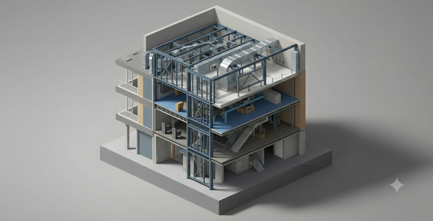
In modern building design, professional mep drafting is the foundational engineering discipline that converts conceptual mechanical, electrical, and plumbing spatial layouts into precise, constructible, and fully coordinated digital drawings. Modern commercial, institutional, and industrial facility projects demand extreme geometric accuracy and technical rigour. Mechanical, electrical, and plumbing (MEP) systems routinely comprise 30% to 60% of total building construction budgets and occupy highly congested physical spaces, such as ceiling plenums, vertical utility shafts, and dedicated plant rooms. Without rigorous drafting protocols, physical system collisions on-site lead to severe construction delays, budget overruns, and compromised structural integrity.
Professional spatial planning requires absolute synchronization across multidisciplinary design teams. Standardized drafting frameworks establish the foundational language through which architectural intent, structural engineering limits, and MEP operational mechanics interface. Comprehensive services covering these integrated multidisciplinary deliverables are accessible through dedicated technical platforms providing specialized MEP plan services, facilitating full compliance with global drafting conventions and building codes.
The transition from traditional two-dimensional vector drafting to object-oriented Building Information Modeling (BIM) has established new paradigms for information management, multi-trade clash detection, and prefabrication detailing. The overarching organization and engineering capabilities provided across the complete design lifecycle are detailed on the primary EngrTeam platform, demonstrating how standardized workflows yield measurable lifecycle efficiencies.
Core Disciplines and Engineering Foundations in MEP Drafting
The process of mep drafting encompasses three distinct yet interdependent engineering domains: mechanical environmental controls, electrical distribution infrastructure, and plumbing or public health utility systems. Each discipline possesses specialized graphic conventions, regulatory mandates, physical space allocations, and spatial priority parameters that must be harmonized within the master drawing set.
Mechanical Systems and HVAC Layout MEP Drafting
Mechanical drafting centers on environmental control, thermal comfort, indoor air quality, and hydronic energy transport. The mechanical draftsperson must account for volumetric air movement, static pressure losses, fluid dynamics, fan acoustics, and equipment vibration isolation. Primary deliverables include supply, return, and exhaust duct layouts, chilled water piping schematics, condenser water loops, boiler room assemblies, and air handling unit (AHU) spatial configurations.
Precision ductwork drafting demands meticulous attention to structural clearances and external insulation thicknesses. Duct fittings—such as transitions, elbows, offsets, turning vanes, and fire dampers—must be drafted with true outer geometry, including flange connections and external insulation buffers. Spatial allocation for mechanical plant equipment requires dedicated zones for filter replacement, coil pullouts, fan shaft removal, and motor maintenance. Detailed strategies for mechanical space optimization and duct routing are executed via specialized HVAC layout plan protocols, ensuring efficient fluid dynamics and compliance with regional mechanical codes.
Electrical Engineering Systems and Distribution MEP Drafting
Electrical system drafting translates complex circuit physics into functional distribution pathways, protection systems, and equipment layouts. Electrical draftspersons handle primary high-voltage distribution, secondary power networks, interior and exterior lighting systems, emergency power generators, uninterruptible power supplies (UPS), and low-voltage communications—including data infrastructure, fire alarm systems, security access control, and building management systems (BMS).
Drafting deliverables span single-line diagrams (SLDs), riser schematics, cable tray routing plans, branch conduit runs, panelboard schedules, and grounding grid details. Cable tray and busduct routing plans must incorporate physical bending radii, clearance access for wire pulling, thermal dissipation buffers, and vertical drop points. The spatial relationship between electrical distribution assets and wet utility systems is strictly governed by safety standards; cable trays and electrical switchboards must never be drafted directly beneath liquid-carrying pipe mains to prevent catastrophic short circuits and structural hazards. Advanced electrical distribution strategies and power density calculations are implemented through certified electrical engineering services, providing robust technical documentation for site execution.
Plumbing and Public Health MEP Drafting Services
Plumbing and public health drafting encompasses domestic cold and hot water supply systems, sanitary drainage, waste venting, storm water management, natural gas distribution, and specialized fire suppression piping networks. Plumbing drafting is uniquely constrained by physical force vectors—specifically gravity-fed drainage gradients.
Unlike pressurized HVAC water lines or flexible electrical conduits, gravity sanitary drainage lines require uninterrupted fall ratios (typically 1:50 or 1:100 slope gradients depending on pipe diameter and code requirements). Consequently, plumbing drainage pathways dictate vertical floor-to-ceiling clearance baselines and cannot be easily diverted around structural obstacles. Plumbing draftspersons produce detailed floor plan layouts, isometric riser diagrams, water supply distribution drafting, domestic hot water recirculating loops, sewage ejector station details, and grease interceptor configurations.
Layer Management and CAD Standardization in MEP Drafting
In computer-aided design (CAD) environments, systematic layer organization is paramount to prevent visual clutter, maintain file performance, and allow seamless cross-disciplinary data sharing. Standardized layer naming schemes ensure that architectural, structural, and MEP engineering drawings maintain uniform graphic hierarchy across different software applications and project teams.
AIA CAD Layer Guidelines for MEP Drafting
The American Institute of Architects (AIA) CAD Layer Guidelines, incorporated into the United States National CAD Standard (NCS), define a hierarchical, alphanumeric layer naming structure. The standard format utilizes distinct data fields separated by hyphens:
Discipline Designator – Major Group – Minor Group 1 – Minor Group 2 – Status
- Discipline Designator: A two-character code identifying the engineering field (e.g.,
Mfor Mechanical,Efor Electrical,Pfor Plumbing,Ffor Fire Protection). Level 2 discipline modifiers provide further specificity (e.g.,MHfor Mechanical Heating,ELfor Electrical Lighting). - Major Group: A four-character field defining the building system or component (e.g.,
DUCTfor Ductwork,LITEfor Lighting,PIPEfor Piping). - Minor Group: Optional four-character fields adding detailed granular description (e.g.,
SUPPfor Supply,LOWRfor Low-Pressure Return,CIRCfor Circuitry). - Status/Phase: An optional single-character field specifying construction status (e.g.,
Nfor New Work,Efor Existing to Remain,Rfor Demolition/Removal).
Examples of standardized AIA layer naming in mep drafting include:
M-DUCT-LOWR-N: Mechanical discipline, Low-Pressure Return Ductwork, New Construction.E-LITE-CIRC-N: Electrical discipline, Lighting Fixture Circuitry, New Construction.P-SANR-PIPE-N: Plumbing discipline, Sanitary Sewer Piping, New Construction.
ISO 13567 Framework for International MEP Drafting
For international projects, ISO 13567 establishes a structured CAD layer standard governed by fixed-length fields. Developed by ISO Technical Committee TC 10 (Subcommittee SC 8), ISO 13567 utilizes a rigid conceptual syntax consisting of mandatory fields (Agent Responsible and Element Graphics) followed by optional fields such as Status, Sector, Phase, Projection, and Work Package.
| CAD Standard Parameter | AIA CAD Layer Guidelines (US NCS) | ISO 13567 Standard (International) |
| Field Structure | Delimited, flexible alphanumeric string | Fixed-length contiguous character string |
| Primary Identifier | 1 or 2 Character Discipline Code (M, E, P) | 2 Character Agent Responsible Code (H, E, C) |
| Element Categorization | 4-Character Mnemonic Major Groups (DUCT, PIPE) | Uniclass / CI/SfB / ISO 12006 Classification Codes |
| Status Field | Optional 1-Character Code (N, E, R, D) | Optional 1-Character ISO Status Code (N, E, R) |
| Global Adoption | Widely adopted across North America & Latin America | Standard across Europe, Asia-Pacific, & Global Projects |
Adherence to strict layering guidelines allows draftspersons to control element visibility, isolate specific building systems during spatial coordination, and apply standardized pen weights, linetypes, and color maps essential for producing legible engineering plots.
Building Information Modeling and ISO 19650 Integration in MEP Drafting
The transition from flat 2D vector drafting to multi-dimensional Building Information Modeling (BIM) has fundamentally altered how MEP spatial data is created, managed, and exchanged. Modern mep drafting relies on parametric 3D modeling platforms such as Autodesk Revit and Navisworks, where graphic elements carry embedded physical, thermal, hydraulic, and electrical metadata.
The ISO 19650 Information Framework for MEP Drafting Workflows
Information management across the digital lifecycle of built assets is standardized globally by the ISO 19650 series. Derived from the British PAS 1192 framework, ISO 19650 defines structured procedures for information exchanges, naming conventions, and model delivery.
Within an ISO 19650-compliant Common Data Environment (CDE), mep drafting models progress through four managed operational states to eliminate data silos and unverified revisions:
- Work in Progress (WIP): Unvalidated model elements maintained locally by specific engineering task teams. For example, a mechanical drafting team updates air duct sizes within its isolated WIP container prior to cross-trade sharing.
- Shared: Validated data released to the broader project team within a centralized coordination space. Structural, architectural, and electrical drafting teams import shared models to evaluate inter-system spatial fits.
- Published: Fully coordinated, verified, and approved engineering models authorized for construction execution, off-site procurement, and structural penetrations.
- Archived: Permanent historical records capturing as-built conditions, contract changes, and point-in-time milestones throughout the asset delivery phase.
Open interoperability schemas maintained by buildingSMART International through Industry Foundation Classes (IFC – ISO 16739) enable vendor-neutral data exchange, ensuring that parametric MEP models remain fully accessible across heterogeneous CAD and BIM software environments.
Levels of Development Specifications in MEP Drafting
In parametric mep drafting, the Level of Development (LOD) framework defines the degree to which a building element’s geometry and associated attribute information have been detailed and finalized.
| Level of Development | Graphic & Geometric Representation | Information & Attribute Content | Practical MEP Drafting Application |
| LOD 100 | Conceptual 3D spatial masses; generic volumetric representations. | Overall area demand; preliminary system capacities. | Feasibility studies; plant room spatial sizing. |
| LOD 200 | Generic system elements; approximate size, shape, and location. | System type, general flow directions, preliminary equipment performance. | Schematic design; early spatial zoning across trades. |
| LOD 300 | Accurate 3D geometry; precise dimensions, routing, slope, and placement. | Detailed engineering parameters, equipment tags, circuit numbers. | Detailed design documentation; preliminary clash tests. |
| LOD 350 | Coordinated geometry including hangers, supports, seismic bracing, & clearances. | Cross-disciplinary clearance requirements, interface connections. | Inter-trade spatial coordination; sign-off for shop drawings. |
| LOD 400 | Fabrication-level geometry; actual manufacturer components, welds, flanges. | Part numbers, cut lengths, spool piece identifiers, fabrication details. | Off-site prefabrication; pipe spool drawings & shop drawings. |
| LOD 500 | Field-verified as-built condition; actual installed location and size. | Maintenance manuals, commissioning dates, serial numbers, COBie data. | Asset management; facility operations & maintenance. |
Transitioning an MEP model from LOD 300 (design intent) to LOD 350 and LOD 400 (fabrication readiness) requires detailed drafting of physical pipe hangers, duct trapezes, thermal expansion loops, flange thicknesses, and equipment access envelopes.
Multi-Trade Coordination and Clash Resolution in MEP Drafting
Spatial coordination is the critical engineering phase where independent architectural, structural, mechanical, electrical, and plumbing models are merged into a unified federated digital environment to identify and eliminate physical and functional space conflicts prior to site mobilization.
Classification of Spatial Clashes in MEP Drafting Models
Automated clash detection engines compare the 3D geometry of every building element against configured rule sets to flag spatial discrepancies. Clashes identified in mep drafting models are categorized into three distinct operational types:
1. Hard Clashes
A hard clash occurs when two or more solid physical objects occupy the exact same three-dimensional space.
- Practical Mechanical Example: A 600mm x 400mm primary supply air duct drafted directly through a structural steel wide-flange beam.
- Practical Plumbing Example: A gravity sanitary drainage main intersecting an electrical cable tray in a congested corridor plenum.
2. Soft (Clearance) Clashes
A soft clash occurs when an element breaches designated clearance buffers required for maintenance access, thermal insulation, safety margins, or operational space, without physically touching another solid object.
- Practical Mechanical Example: An uninsulated chilled water pipe drafted too close to a hot condenser water line, causing unwanted thermal gain, or ductwork blocking filter panel doors on an Air Handling Unit.
- Practical Electrical Example: A high-voltage panelboard placed without the code-mandated 1-meter front clearance zone, or a cable tray mounted directly against a ceiling slab, preventing future wire pulling.
3. Workflow (4D / Sequencing) Clashes
A workflow clash involves time-space sequencing conflicts during construction staging, where trade activities or installation schedules conflict.
- Practical Construction Example: Enclosing a structural concrete block wall before large centrifugal chillers or boilers are rigged into a basement plant room, or scheduling ceiling grid installation prior to high-level primary ductwork placement.
The Eight-Step Clash Resolution Cycle in MEP Drafting
To resolve design conflicts systematically without creating secondary clashes in adjacent zones, engineering teams execute a structured eight-step clash detection cycle:
- Model Federation: Combine individual discipline CAD/BIM models (Architecture, Structure, Mechanical, Electrical, Plumbing, Fire Protection) into a shared coordinate space utilizing unified project origin points.
- Selection Set Creation: Group elements by system, discipline, floor level, and zone to execute targeted tests rather than running undifferentiated global checks.
- Rule Set and Tolerance Configuration: Establish geometric tolerances (e.g., ignoring hard overlaps under 5mm or setting soft maintenance zones to 600mm) and exclude intentional connections (such as pipe fittings touching pipes).
- Automated Test Execution: Execute discipline-pair tests in structured priority order (e.g., Mechanical vs. Structure, Plumbing vs. Electrical).
- Triage, Grouping, and Filtering: Filter out false positives (e.g., approved slab sleeves, nested components) and group multi-clash instances caused by a single misrouted duct into a single actionable issue.
- Priority Assignment and Issue Tracking: Assign clashes to responsible trade leads with assigned ownership, resolution deadlines, and 3D viewpoints using Building Collaboration Format (BCF) open standards.
- Rerouting and Model Adjustment: Reroute systems following established spatial hierarchy rules.
- Re-Testing and Validation: Re-federate modified models, re-run tests to confirm resolution, and verify that adjustments did not generate new secondary clashes in adjacent zones.
Spatial Priority Rules in MEP Drafting
When resolving hard clashes between overlapping utilities, draftspersons follow a strict spatial priority hierarchy established in the project BIM Execution Plan (BEP). The general principle dictates that unyielding, expensive, or gravity-dependent systems retain right-of-way over flexible or pressurized utilities.
| Priority Rank | Utility Discipline / System | Engineering Spatial Priority Rationale |
| 1 | Structural Beams, Columns, & Shear Walls | Primary load-bearing elements; non-negotiable geometry. |
| 2 | Gravity Drainage & Sloped Sewer Piping | Unpressurized gravity fall cannot be rerouted without risking stagnant flow. |
| 3 | Primary Mechanical Ductwork Mains | Large cross-sectional volume; high energy penalties if extra bends/offsets are added. |
| 4 | High-Voltage Electrical Busducts & Main Trays | Rigid, high-cost components with strict bending radius parameters. |
| 5 | Pressurized Hydronic & Domestic Water Lines | Pressurized fluid can easily navigate around obstacles via elbows and drops. |
| 6 | Small Electrical Conduits & Branch Sprinklers | Highly flexible routing; small diameter footprint easily adjusted on site. |
Off-Site Prefabrication and Shop Drawings in MEP Drafting
As mep drafting progresses from spatial coordination (LOD 350) to field construction readiness (LOD 400), deliverables shift toward fabrication-level shop drawings, pipe spool sheets, and installation sleeve plans.
Pipe Spool Detailing and Modular Fabrication in MEP Drafting
Pipe spool drawings are specialized shop drawings created for off-site pipe fabrication. A spool represents a prefabricated sub-assembly of pipe lengths, fittings, flanges, structural supports, and valves welded together in a controlled factory environment prior to delivery to the job site.
┌─────────────────────────────────────────────────────────────────────────────────┐
│                      PIPE SPOOL ASSEMBLY SPECIFICATION                          │
├─────────────────────────────────────────────────────────────────────────────────┤
│                                                                                 │
│   [ Flange A ] ═══ ( Pipe Segment 1 ) ═══ [ Weld Fitting ]                      │
│                                                  ║                              │
│                                           ( Pipe Segment 2 )                    │
│                                                  ║                              │
│                                            [ Flange B ]                         │
│                                                                                 │
└─────────────────────────────────────────────────────────────────────────────────┘
Precision pipe spool drafting yields several major field advantages:
- Exact Dimensional Tolerance: Spool drawings display precise cut lengths, bevel angles, weld locations, and fitting orientation angles (roll angles).
- Weld Categorization: Drafting explicitly differentiates shop welds (executed in factory conditions) from field welds (executed on site during final tie-ins).
- Bill of Materials (BOM): Automated data extraction lists itemized schedules of pipe schedules, material specifications (e.g., ASTM A53 Carbon Steel, Copper Type L, Stainless Steel 316), pressure ratings, and gasket types.
- Quality Assurance & Testing Data: Spool sheets incorporate pressure test specifications (hydrostatic or pneumatic limits) and non-destructive examination (NDE) requirements.
Off-site prefabrication driven by high-precision spool drafting drastically reduces field labor hours, minimizes material waste, improves weld quality, and enhances site safety.
Sleeving, Inserts, and Hanger Penetration Layout MEP Drafting
Before concrete floor slabs and shear walls are poured on site, MEP draftspersons must produce accurate sleeve, insert, and hanger penetration drawings.
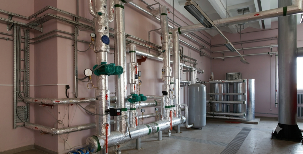
Sleeve layout drawings specify exact dimensioned offsets from structural gridlines for all floor and wall penetrations required for pipe risers, duct mains, and cable trays. Drafting details must include annular space allowances for pipe insulation and firestop assemblies, ensuring that core-drilling or post-construction structural hacking is completely eliminated.
Quality Assurance and Technological Horizons in MEP Drafting
Achieving long-term asset value requires rigorous quality control (QC) procedures during drawing production, paired with an understanding of emerging technologies shaping digital AEC workflows.
Quality Control Procedures and Metadata Auditing in MEP Drafting
Before issuing MEP drawings for construction, engineering teams conduct multi-stage quality audits to verify graphical accuracy and data integrity:
- Visual Graphic Standards Verification: Audit title blocks, scale declarations, annotation font consistency, dimension callout readability, and pen weight hierarchies.
- Discipline Code Compliance: Validate that drawing designs comply with international, national, and regional codes (e.g., ASHRAE standards for HVAC, NFPA regulations for fire suppression, National Electrical Code (NEC), and LEED sustainability metrics).
- Model Metadata Health Checks: Scan parametric BIM families for unmapped parameters, duplicate element IDs, unconstrained geometry, or missing classification codes (Uniclass/OmniClass).
- Vector Consistency and Coordinate Audits: Ensure project origin points, shared site coordinates, and elevation datums strictly align across all CAD xrefs and federated BIM models.
Artificial Intelligence and Digital Twin Integration in MEP Drafting
The future of mep drafting is increasingly automated through Artificial Intelligence (AI) algorithms, generative design, and IoT-connected Digital Twins.
- Generative Spatial Routing: Machine learning algorithms automatically calculate optimal 3D routes for complex duct and pipe networks around structural barriers while adhering to pressure drop limits, clearance rules, and cost parameters.
- Automated ISO Compliance Validation: AI-based quality audit tools automatically review CAD layers and BIM parameter fields against ISO 19650 and ISO 13567 standards, automatically flagging non-compliant elements.
- Digital Twin Handover (ISO 19650-3): Post-construction MEP drafting models are linked directly to real-time Internet of Things (IoT) sensors installed within building systems. The synchronized Digital Twin allows facility managers to monitor real-time flow rates, filter pressure drops, electrical loads, and equipment temperatures, triggering predictive maintenance alerts long before component failures occur.
Strategic Value of Precision MEP Drafting in Built Asset Lifecycles
Precise mep drafting represents the ultimate bridge between conceptual engineering design and physical building assembly. By establishing standardized layer structures (AIA / ISO 13567), operating within unified ISO 19650 Common Data Environments, and executing disciplined multi-trade clash detection, AEC professionals eliminate spatial conflicts on paper and in digital models rather than on the job site.
The quantitative benefits of high-precision mep drafting extend across the entire lifecycle of built assets: construction teams achieve up to a 90% reduction in field rework, procurement teams minimize material waste through prefabrication spool sheets, and facility owners gain data-rich, field-verified as-built models essential for optimized operational asset management. As building systems grow in complexity, standardized and coordinated mep drafting remains the cornerstone of modern engineering excellence and sustainable facility design.







