

Articles
HVAC Heat Load Calculation: The Ultimate Engineering Guide

HVAC heat load calculation is the foundational engineering process used to determine the exact amount of heating and cooling energy
Table of Contents
HVAC heat load calculation is the foundational engineering process used to determine the exact amount of heating and cooling energy required to maintain a building within comfortable, code-compliant indoor environmental parameters. In contemporary architecture and mechanical engineering, relying on outdated rules of thumb—such as allocating a fixed tonnage per square foot—frequently leads to severe system oversizing or undersizing. Oversized heating, ventilation, and air conditioning (HVAC) systems short-cycle, wasting energy and failing to dehumidify indoor air properly, while undersized systems run continuously without reaching thermostat setpoints during peak weather extremes.
Mastering the science and methodology of thermal load analysis ensures optimal indoor air quality, energy efficiency, equipment longevity, and strict compliance with international building standards.
1. Fundamentals of HVAC Heat Load Calculation
At its core, thermal load analysis is governed by the laws of thermodynamics. Heat naturally flows from warmer zones to cooler zones via three primary mechanisms: conduction, convection, and radiation. An accurate engineering assessment accounts for how these energy transfers interact across a building’s exterior envelope and interior spaces under both winter heating and summer cooling design conditions.
The Role of Thermal Thermodynamics in Building Design
Buildings are dynamic thermal systems influenced by daily solar cycles, outdoor ambient temperature swings, shifting wind pressures, and internal heat generation from occupants and electrical equipment. The objective of calculating thermal loads is to quantify the net rate of heat loss (in winter) and heat gain (in summer), measured in British Thermal Units per hour (BTU/hr) or kilowatts (kW).
For professional design strategies and multi-disciplinary mechanical systems, explore comprehensive resources at Engineer’s Team.
3. Core Components of Heat Gain and Loss
A rigorous thermal load assessment divides energy transfer into distinct physical components. Each factor must be calculated separately on a room-by-room basis to ensure balanced air distribution.
Exterior Envelope (Walls, Roofs, and Floors)
Heat transfer through solid opaque structures occurs primarily via conduction. The rate of conductive heat flow depends on the surface area ($A$), the temperature difference ($\Delta T$) across the assembly, and the thermal resistance (R-value or U-factor) of the materials:
$$Q = U \times A \times \Delta T$$
Engineers evaluate composite assemblies—including exterior brick, concrete masonry units (CMU), continuous exterior insulation, wood or steel studs, cavity insulation, and interior drywall—to determine overall U-factors in strict compliance with ASHRAE standards.
Fenestration: Windows, Skylights, and Glass Doors
Glass areas represent the most thermally sensitive components of any building envelope. Heat gain through windows is twofold:
-
Conductive Transfer: Driven by the temperature difference between outdoor ambient air and conditioned indoor air, governed by the window U-factor.
-
Solar Radiation Gain: Driven by direct sunlight passing through glazing, quantified by the Solar Heat Gain Coefficient (SHGC) and shading coefficients. West- and south-facing windows receive intense solar radiation during peak afternoon hours, significantly spiking cooling loads.
Infiltration and Ventilation Air
Air leakage (infiltration) occurs through cracks around doors, window frames, building joints, and envelope penetrations driven by wind pressure and stack effect. Furthermore, indoor air quality codes mandate fresh outdoor ventilation air to dilute carbon dioxide and indoor pollutants. Bringing in untreated outdoor air requires substantial thermal energy to heat or cool and dehumidify it before it enters occupied zones.
Internal Heat Gains
Occupants generate sensible heat through metabolic activity and latent heat through respiration and perspiration. Additionally, modern commercial and residential buildings contain high concentrations of internal heat sources, including:
-
Lighting Systems: Energy consumed by LED and fluorescent fixtures that converts into ambient heat.
-
Appliances and Electronics: Computers, servers, kitchen equipment, televisions, and office machinery.
-
Motors and Equipment: Pumps, elevators, and machinery operating within conditioned boundaries.
Sensible vs. Latent Heat Loads
A critical distinction in cooling load calculations is separating sensible heat from latent heat.
Sensible Heat Load
Sensible heat refers to thermal energy that causes a measurable change in air temperature, registered directly by a standard dry-bulb thermometer. Sources of sensible heat include solar radiation through glass, conduction through walls and roofs, lighting, occupants, and appliances.
Latent Heat Load
Latent heat refers to thermal energy associated with moisture in the air (humidity). When water vapor enters a space through occupant respiration, cooking, showers, indoor plants, or humid outdoor infiltration, it adds latent load without raising the dry-bulb temperature. The cooling equipment must condense this moisture out of the air via the evaporator coil.
The ratio of sensible heat to total heat is known as the Sensible Heat Ratio (SHR). In humid climates, equipment must be selected with a lower SHR to ensure adequate moisture removal, preventing damp, clammy indoor conditions.
Standard Methodologies and Governing Guidelines
Professional HVAC design is anchored in standardized engineering guidelines published by recognized institutions.
ACCA Manual J
For residential and low-rise light commercial structures, the Air Conditioning Contractors of America (ACCA) Manual J is the North American benchmark protocol for calculating peak heating and cooling loads. It establishes standardized calculation forms and computer software algorithms that account for local 99% winter and 1% summer weather design temperatures, building orientation, duct location, and envelope insulation grades.
ASHRAE Fundamentals and Handbook
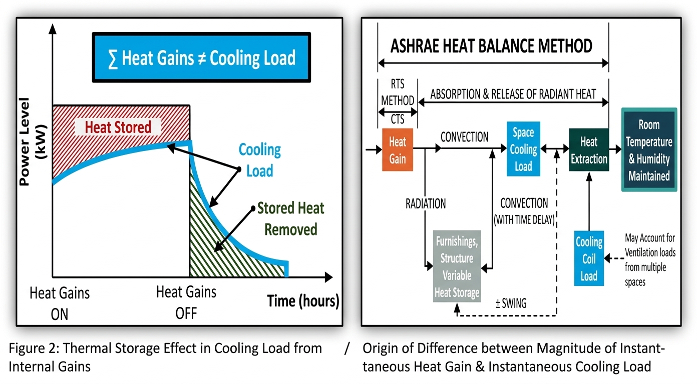
For complex commercial, industrial, institutional, and high-rise structures, mechanical engineers rely on the comprehensive calculation procedures outlined in the ASHRAE Handbook – Fundamentals. These guidelines provide advanced psychrometric equations, transfer function methods (TFM), and radiant time series (RTS) methods for dynamic cooling load analysis. Technical standards and ongoing research maintained by organizations such as ASHRAE govern modern building energy efficiency and environmental control benchmarks worldwide.
Step-by-Step Engineering Calculation Workflow
Executing an accurate thermal load analysis follows a structured, sequential workflow:
-
Gather Architectural and Civil Data: Collect floor plans, elevations, section details, window schedules, insulation specifications, and compass orientations.
-
Determine Local Weather Design Conditions: Look up official winter heating and summer cooling design temperatures, elevation, and daily temperature ranges for the specific geographic location.
-
Establish Envelope Thermal Properties: Calculate R-values and U-factors for all exterior walls, roofs, ceilings, foundations, and glazing assemblies.
-
Input Building Geometry Room-by-Room: Model the structure in approved software, defining room dimensions, ceiling heights, exterior wall exposures, and door sizes.
-
Calculate Infiltration and Ventilation Rates: Apply Blower Door test results or standard code air-change rates to quantify incoming unconditioned air volumes.
-
Quantify Internal Gains: Enter occupant counts, operating schedules for lighting, appliances, and equipment heat dissipation.
-
Generate Peak Load Reports: Run the computational algorithm to extract peak heating and cooling loads for each individual room and for the overall building block. For specialized duct routing and mechanical distribution strategies, review professional insights regarding an HVAC layout plan.
Software and Computational Tools
While manual calculations using spreadsheets were once standard practice, modern MEP engineering relies heavily on sophisticated software tools. Software packages such as Wrightsoft Right-Suite Universal, Elite Rhvac, Trane Trace 700 / 3D Plus, Carrier HAP (Hourly Analysis Program), and Cool Calc allow engineers to model complex thermal zones, simulate hourly weather changes, and optimize equipment sizing with speed and precision.
Common Pitfalls and Rules of Thumb Dangers
Relying on outdated estimation methods introduces significant engineering risks. Common mistakes include:
-
Using Square-Footage Rules of Thumb: Assuming “one ton per 500 sq. ft.” ignores window orientation, insulation quality, and local climate variations.
-
Ignoring Duct Heat Gain/Loss: Forgetting that ducts running through unconditioned attics or crawlspaces add massive thermal loads to the air distribution system.
-
Failing to Account for Solar Shading: Neglecting exterior overhangs, neighboring structures, or Low-E window coatings that dramatically reduce solar heat gain.
-
Oversizing Equipment “Just in Case”: Installing a larger unit than calculated, which causes short-cycling, high humidity, indoor mold growth, and premature compressor failure.
Conclusion
Carrying out an accurate hvac heat load calculation is the single most important step in designing an efficient, comfortable, and reliable building mechanical system. By moving away from guesswork and embracing rigorous engineering standards, builders, architects, and mechanical consultants ensure optimal indoor climate control, reduced energy consumption, and long-term asset value.
- Tags: heat air, hvac load calculation
Recent Posts
- HVAC Heat Load Calculation: The Ultimate Engineering Guide
- Hydronic Heat Load Calculation Service: The Ultimate Guide to Precision Heating Design
- Manual J D S: The Complete HVAC Load, Duct, and Equipment Sizing Guide
- Cool Calc Manual D: The Ultimate Guide to HVAC Duct Design and Sizing
- Understanding the Core Roles: Difference Between HVAC Designer and MEP Engineer