

Articles
Hydronic Heat Load Calculation Service: The Ultimate Guide to Precision Heating Design

A hydronic heat load calculation service delivers the precise mathematical foundation required to design, size, and install efficient closed-loop liquid
Table of Contents
A hydronic heat load calculation service delivers the precise mathematical foundation required to design, size, and install efficient closed-loop liquid heating systems. In modern residential, commercial, and industrial construction, relying on antiquated rules of thumb—such as arbitrary square-footage sizing—leads to severe mechanical inefficiencies, boiler short-cycling, uneven room temperatures, and exorbitant energy bills. Whether you are engineering a multi-zone radiant floor heating network, sizing a condensing boiler plant for a commercial complex, or integrating hydronic coils into a complex air handling unit, accurate heat loss modeling is the single most critical determinant of system performance.
This comprehensive guide explores the core principles, engineering methodologies, hydraulic balancing techniques, equipment sizing criteria, and long-term economic benefits of utilizing a professional hydronic heat load calculation service.
1. Introduction to Hydronic Heating and Thermal Dynamics
Hydronic heating systems circulate heated water or a water-glycol solution through a closed network of pipes, distribution manifolds, and terminal units—such as radiant floor tubing, cast-iron radiators, panel radiators, fin-tube baseboards, and fan coil units. Water possesses a volumetric heat capacity approximately 3,500 times greater than air, making hydronic distribution an exceptionally efficient method for transporting thermal energy across a building.
However, the thermodynamic efficiency of a hydronic system depends entirely on how accurately the heat losses of the building are calculated. Every building structure constantly loses heat to the surrounding cold outdoor environment through conduction, convection, and air infiltration. A professional engineering calculation balances these thermal losses by determining the exact British Thermal Units per hour (BTU/hr) or kilowatts (kW) required for every individual room under peak winter design conditions.
2. What is a Hydronic Heat Load Calculation Service?
A hydronic heat load calculation service is a specialized engineering service that computes room-by-room heating requirements using advanced building science software and governing industry standards (such as ACCA Manual J, ISO 11855, or CIBSE guidelines).
Instead of treating a building as a single homogeneous block, professional engineering consultants analyze the physical characteristics of every room and zone. This includes quantifying heat transfer through exterior walls, windows, doors, ceilings, roof assemblies, slabs-on-grade, and basement foundation walls. Furthermore, the calculation incorporates air infiltration rates, stack effect, mechanical ventilation fresh-air requirements, and specific geographic winter weather data.
The output of this service provides mechanical contractors and designers with the exact peak heating load for each room, total boiler capacity requirements, water flow rates (GPM), pressure drops (feet of head), and individual circuit manifold schedules.
3. The Core Components of a Hydronic Load Calculation
To construct an accurate hydronic thermal model, engineers evaluate several distinct heat loss pathways. Understanding these components clarifies why professional calculation services are indispensable.
Transmission Heat Losses (Conduction)
Transmission loss refers to heat escaping directly through solid building materials driven by the temperature difference between the warm indoor air and the cold outdoor climate. The rate of transmission heat loss is governed by the fundamental Fourier’s law of heat conduction, expressed through the thermal transmittance (U-factor) or thermal resistance (R-value) of each assembly:
$$Q = U \times A \times \Delta T$$
Where $Q$ is heat loss (BTU/hr), $U$ is the U-factor ($\text{BTU/hr}\cdot\text{ft}^2\cdot^\circ\text{F}$), $A$ is surface area ($\text{ft}^2$), and $\Delta T$ is the design temperature difference ($^\circ\text{F}$). Engineers calculate transmission losses separately for:
-
Above-grade exterior walls (wood frame, steel stud, masonry, EIFS, or concrete).
-
Windows and glazed doors (accounting for glass U-factor and frame thermal breaks).
-
Roof and ceiling assemblies (attic insulation, vaulted ceilings, and flat roof decks).
-
Foundation walls and slab edges (below-grade concrete or crawlspace perimeters).
Infiltration and Ventilation Losses
Cold outdoor air constantly enters a building through cracks, door gaps, and window seals (infiltration) or is intentionally introduced via mechanical fresh-air ventilation systems (ventilation). Heating this incoming outdoor air to indoor comfort temperatures requires significant thermal energy. The sensible heat loss due to air exchange is calculated using the standard formula:
$$Q_{\text{air}} = 1.08 \times \text{CFM} \times \Delta T$$
Where $\text{CFM}$ represents the cubic feet per minute of outside air entering the space. Accurate infiltration values are derived from building airtightness testing (such as Blower Door ACH50 metrics) or construction tightness classifications.
Intermittent Pick-Up Factors
In certain commercial buildings or intermittent heating zones (such as churches, offices, or schools that experience setback temperatures at night), the hydronic system must possess extra capacity to rapidly reheat the space upon morning startup. Engineering calculations factor in customized pick-up allowances to ensure boilers are not undersized for recovery periods.
4. Step-by-Step Methodology of Professional Hydronic Calculations
Executing a rigorous hydronic calculation follows a disciplined engineering workflow from initial data acquisition to final reporting.
Step 1: Climate Analysis and Design Temperatures
Engineers look up official meteorological weather data for the specific project location. For heating design, the 99% winter dry-bulb design temperature is selected. This represents the outdoor temperature that is equaled or exceeded 99% of the total hours during the three coldest winter months, ensuring the system can maintain comfort even on the most severe winter nights.
Step 2: Architectural Takeoffs and Envelope Profiling
Detailed floor plans, structural sections, and window schedules are analyzed to catalog every surface separating conditioned space from unconditioned space or the outdoors. Orientation is also factored in, as windward walls experience accelerated convective heat loss.
Step 3: Room-by-Room Calculations
Software models compute the net heat loss for every individual room. This room-by-room breakdown is vital because different rooms have vastly different heat loss profiles. For instance, a bathroom with tile flooring and an exterior wall requires a high BTU/hr output per square foot, whereas an interior bedroom with minimal exterior exposure requires very little heating energy.
Step 4: Aggregation and System Safety Factors
Individual room loads are summed to determine the total building peak heating load. A professional engineering service then applies appropriate piping loss factors and system safety margins to establish the exact net and gross output requirements for the boiler plant.
5. Equipment Sizing and Boiler Selection Principles
Once the peak hydronic heat load is established, engineers transition to selecting the primary heating appliances, ensuring optimal efficiency and longevity.
Condensing vs. Non-Condensing Boilers
Modern hydronic design heavily favors high-efficiency condensing boilers. Condensing boilers extract latent heat from water vapor in the flue gases by cooling the exhaust below its dew point (typically below 130°F / 54°C return water temperatures), achieving Annual Fuel Utilization Efficiencies (AFUE) or thermal efficiencies exceeding 95% to 98%. Engineering calculations ensure that water temperature drop design parameters allow the boiler to condense for the majority of the heating season.
Avoiding Boiler Oversizing
A common mistake among untrained installers is doubling the boiler capacity “just to be safe.” Oversizing a boiler causes severe short-cycling—the burner fires at high output for only a few minutes, satisfies the small load quickly, and shuts down. Short-cycling wastes fuel, elevates combustion emissions, subjects heat exchangers to extreme thermal stress, and drastically shortens equipment lifespan. A precise calculation service eliminates guesswork, matching boiler modulation ranges directly to actual building loads.
6. Flow Rates, Pipe Sizing, and Hydraulic Balancing
Heat generated at the boiler must be transported efficiently to every terminal emitter across the building. This requires meticulous hydraulic calculations.
Calculating Required Circulator Flow Rates (GPM)
The circulating water flow rate in Gallons Per Minute (GPM) is determined by the total room heating load and the design water temperature drop ($\Delta T$, typically between 15°F and 30°F):
$$\text{GPM} = \frac{\text{Total BTU/hr}}{500 \times \Delta T}$$
For radiant floor systems, lower $\Delta T$ values (e.g., 10°F to 15°F) are often used to maintain even floor surface temperatures, whereas baseboard and radiator systems utilize higher $\Delta T$ values (e.g., 20°F) to optimize pipe sizing.
Head Loss and Pipe Sizing
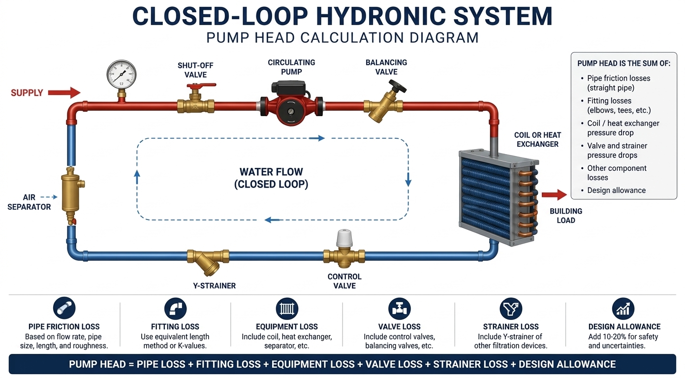
As water travels through PEX tubing, copper piping, fittings, valves, boilers, and heat emitters, it encounters friction resistance (head loss), measured in feet of water head per 100 feet of pipe. Engineers calculate the Total Equivalent Length of the longest piping circuit to select circulator pumps that deliver the exact required flow against total system resistance without causing high-velocity water noise or erosion corrosion.
7. Radiant Floor Heating vs. Convector and Radiator Systems
Different terminal emitters operate at drastically different supply water temperatures, which directly influences hydronic design parameters.
Radiant Floor Heating Systems
Radiant floor heating embeds PEX tubing within concrete slabs, gypsum underlayments, or modular plate systems. Because the entire floor acts as a low-temperature heating panel, radiant systems operate efficiently with supply water temperatures between 90°F and 120°F. Calculating loads for radiant floors requires evaluating floor covering thermal resistance (R-value of carpets, hardwood, or tile), tube spacing (6, 9, or 12 inches on center), and maximum allowable floor surface temperatures (typically 85°F for comfort and barefoot safety).
Cast-Iron Radiators and Fin-Tube Baseboards
Conventional radiators and baseboards operate at medium-to-high water temperatures (140°F to 180°F). Heat load calculations must verify that the linear footage of baseboard or the radiator section count installed in each room matches the exact BTU loss calculated at design water temperatures.
8. Common Pitfalls in Hydronic Design and How to Avoid Them
Failing to engage a professional hydronic calculation service frequently results in critical system failures during freezing weather.
| Common Hydronic Design Mistake | Engineering Consequence | Professional Solution |
| Using Square-Foot Rules of Thumb | Undersizes heating in drafty rooms or severely oversizes boilers, causing short-cycling and high gas bills. | Execute rigorous room-by-room Manual J or ISO heat loss modeling. |
| Ignoring Domestic Hot Water (DHW) Priority Loads | When the indirect water heater calls for priority heating, space heating drops, causing indoor temperatures to plummet. | Calculate combined domestic water and space heating peak loads when sizing boiler inputs. |
| Inadequate Hydraulic Separation | Variable-speed zone circulators fight against the primary boiler pump, causing flow starvation and erratic heating. | Design primary-secondary piping loops or hydraulic low-loss headers with proper manifold zoning. |
| Neglecting Floor Covering Thermal R-Values | Thick carpets and heavy underpads insulate radiant tubing, trapping heat and leaving rooms cold. | Factor surface thermal resistance directly into radiant floor hydronic calculations. |
9. Industry Standards, Codes, and Technical Resources
Professional hydronic engineering is governed by established codes and international design standards that ensure safety, efficiency, and structural integrity.
Building codes such as the International Mechanical Code (IMC) and International Energy Conservation Code (IECC) mandate proper sizing and efficiency documentation for all residential and commercial heating installations. Engineering consultants rely on technical guidance from global authorities such as the American Society of Heating, Refrigerating and Air-Conditioning Engineers (ASHRAE), which publishes comprehensive handbooks on HVAC systems, heating loads, and hydronic piping design. Adhering to these rigorous standards ensures compliance with local municipal permit requirements and qualifies systems for top-tier energy rebates.
10. Leveraging Expert MEP Engineering for Your Project
Integrating a complex hydronic heating system requires seamless coordination between architectural design, structural engineering, and mechanical layout planning. From calculating precise room-by-room heat losses and balancing multi-zone manifolds to selecting high-efficiency condensing boiler plants, professional oversight guarantees absolute comfort and reliability.
To explore comprehensive engineering solutions, mechanical blueprints, and specialized technical support for your upcoming construction project, visit our professional MEP plan services page.
11. Conclusion
A professional hydronic heat load calculation service is the cornerstone of any high-performance heating installation. By replacing outdated guesswork with rigorous thermodynamics, fluid dynamics, and room-by-room thermal modeling, building owners, architects, and mechanical contractors can achieve optimal energy efficiency, whisper-quiet operation, and unwavering comfort. Investing in accurate calculations upfront eliminates costly field modifications, prevents equipment pre-mature failure, and guarantees long-term heating excellence.
Recent Posts
- Hydronic Heat Load Calculation Service: The Ultimate Guide to Precision Heating Design
- Manual J D S: The Complete HVAC Load, Duct, and Equipment Sizing Guide
- Cool Calc Manual D: The Ultimate Guide to HVAC Duct Design and Sizing
- Understanding the Core Roles: Difference Between HVAC Designer and MEP Engineer
- 3D Modeling and Rendering Services in UK: The Ultimate Architectural Guide