

Articles

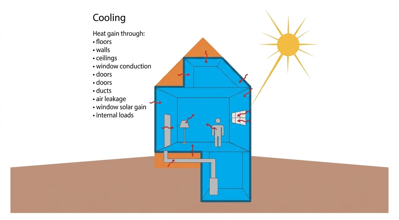
An HVAC load calculation service delivers the exact thermodynamic analysis needed to size heating and cooling equipment for residential and commercial buildings. Far too often, heating, ventilation, and air conditioning (HVAC) systems are sized using outdated rules of thumb—such as allocating one ton of cooling per 500 square feet. This crude approach ignores modern insulation standards, window efficiency, building orientation, infiltration rates, and internal thermal loads.
Selecting an HVAC system based on imprecise guesses leads to inflated utility bills, premature equipment failure, poor humidity control, and persistent occupant discomfort. A professional engineering load calculation eliminates guesswork by calculating the exact BTUs (British Thermal Units) required to maintain comfortable indoor conditions under peak design parameters.
What is an HVAC Load Calculation Service?
An HVAC load calculation service is a specialized engineering process that quantifies the precise rate at which heat is added to or removed from a building space to maintain target indoor temperature and relative humidity. Performed by mechanical engineers and certified energy assessors, this service evaluates every structural, environmental, and operational dynamic of a property.
and Heat Gain Engine
Defining Heating and Cooling Loads
The mechanical heating and cooling requirements of any structure fall into two primary thermal load categories:
- Heating Load: The total amount of heat energy (measured in BTU/hr or Watts) that escapes through the building envelope during cold weather. The heating system must generate and supply an equal amount of heat to maintain the desired indoor setpoint.
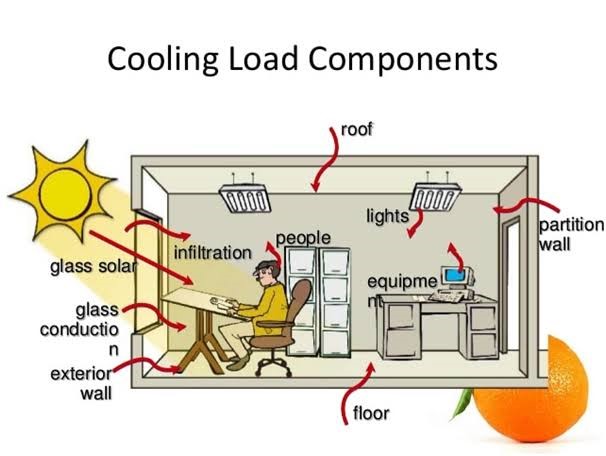
- Cooling Load: The total amount of heat energy that enters the building envelope from external weather conditions plus heat generated internally from occupants, electronics, and lighting. The cooling system must extract this heat at an equivalent rate.
Heat Loss vs. Heat Gain: The Physics of Thermal Transfer
Thermal energy naturally migrates from regions of higher temperature to regions of lower temperature via three primary mechanisms:
- Conduction: Heat transfer through solid building materials, such as walls, roofs, slab floors, and glass panes. Conduction is governed by Fourier’s Law of Heat Conduction:Q₍conduction₎ = U × A × ΔT
- Where Q is heat loss or gain (BTU/hr), U is the thermal transmittance factor, A is the surface area (ft²), and ΔT is the indoor-outdoor temperature differential (°F).
- Convection: Thermal energy transferred via fluid movement—specifically air movement. Warm air rising, cold drafts penetrating building gaps, and mechanical air movement across heat exchangers are driven by convection.
- Radiation: Thermal radiation transmitted via electromagnetic waves. The primary driver of radiant heat gain in buildings is direct solar radiation passing through glass windows or heating up exterior roof surfaces.
Furthermore, cooling load calculations must account for two distinct types of heat energy:
- Sensible Heat: The energy associated with changing dry-bulb air temperature without changing moisture content. Examples include sunlight heating a floor or heat given off by a radiator.
- Latent Heat: The energy associated with moisture in the air (humidity). Latent heat loads arise from human respiration, cooking, bathing, outdoor air infiltration, and dedicated fresh air ventilation. The HVAC system removes latent heat by condensing water vapor across a cooling coil.
Why “Rule of Thumb” Sizing Fails
Historically, HVAC contractors selected equipment size using simple area-based estimates, such as1 ton (12,000 BTU/hr) = 500 sq. ft. While this shortcut saved time, it produces significant sizing errors for modern structures:
- Envelope Advances: A modern home built with spray-foam insulation, low-E triple-pane windows, and airtight construction might only require 1 ton per 1,000–1,200 sq. ft. Using a 500 sq. ft. rule results in an oversized system that short-cycles continuously.
- Orientation Differences: Two identical homes built side-by-side will have vastly different cooling loads if one features extensive west-facing glass while the other faces north.
- Climate Variations: A 2,500 sq. ft. building in hot, humid Houston, Texas presents completely different latent and sensible load profiles than an identical building in dry, high-altitude Denver, Colorado.
Relying on rule-of-thumb sizing leads to poor comfort, high energy consumption, and equipment failures. A comprehensive HVAC load calculation service replaces guesses with rigorous, code-approved thermodynamic calculations.
The ACCA Industry Protocols: Manual J, S, D, and N Explained
In the United States and globally, the Air Conditioning Contractors of America (ACCA) standards establish the recognized methodology for calculating heating and cooling loads and designing air distribution systems. A professional HVAC load calculation service adheres directly to these established protocols.
| ACCA Manual Standard | Scope & Purpose | Primary Engineering Deliverable |
| Manual J | Residential Load Calculation | Whole-house and room-by-room heating/cooling BTU loads |
| Manual S | Equipment Selection | Matching HVAC equipment capacities to Manual J loads |
| Manual D | Residential Duct Design | Sizing supply/return ducts, trunk lines, and registers (CFM) |
| Manual N | Commercial Load Calculation | Commercial building thermal loads, zoning, and diversity |
| Manual Q | Commercial Duct Design | Low-pressure, high-velocity commercial air distribution systems |
ACCA Manual J – Residential Load Calculation
Manual J is the industry standard for calculating residential heating and cooling loads. It evaluates heat gain and loss room by room, ensuring every space receives sufficient conditioned air.
- Whole-House Manual J: Calculates the total peak heating and cooling requirements for the entire building envelope. This total figure determines the required capacity of central air conditioners, heat pumps, or furnaces.
- Room-by-Room Manual J: Breaks down heat loss and heat gain for every individual room. This detail is essential for balancing ductwork, selecting branch duct sizes, and determining terminal air volumes (CFM) for individual supply registers.
ACCA Manual S – Equipment Selection & Matching
Once the precise BTU heating and cooling loads are established via Manual J, the designer applies ACCA Manual S to select appropriate mechanical equipment.
Equipment selection is not as simple as picking a 3-ton air conditioner for a 36,000 BTU cooling load. HVAC unit performance varies significantly based on local outdoor design temperatures, entering wet-bulb temperatures, and indoor fan speeds. Manual S prevents contractors from oversizing equipment to match nominal manufacturer values, enforcing strict limits:
- Cooling Equipment Sizing Limit: Total cooling capacity generally must not exceed 115% of the calculated Manual J total cooling load (or up to 125% for variable-speed heat pumps).
- Heating Equipment Sizing Limit: Heating capacity generally must not exceed 140% of the calculated Manual J heating load.
ACCA Manual D – Residential Duct Design & Airflow Engineering
An HVAC system cannot deliver comfortable temperatures without a properly engineered distribution system. ACCA Manual D takes the room-by-room CFM requirements derived from Manual J and uses them to design the ductwork system.
Manual D accounts for total effective length (TEL), available static pressure (ASP), friction rates, blower performance curves, and velocity limits across main trunks and branch runouts. Coupling a Manual J calculation with a Manual D layout ensures proper static pressure and quiet, balanced airflow throughout the building. For comprehensive drafting and system integration, an accurate HVAC layout plan translates these engineered airflow figures into clear, installable CAD/BIM drawings.
ACCA Manual N – Commercial Load Calculation
Commercial buildings feature operational profiles that differ fundamentally from single-family homes. ACCA Manual N addresses commercial structures—such as retail spaces, offices, warehouses, and religious facilities—by incorporating specialized variables:
- Occupancy Schedules & Diversity: Accounting for varying floor occupancy across different times of day.
- Ventilation Standards: Integrating outdoor air requirements compliant with ASHRAE Standard 62.1.
- Complex Internal Gains: Factoring in server racks, commercial kitchen equipment, fluorescent/LED lighting arrays, and manufacturing machinery.
- Multi-Zone Dynamics: Evaluating varying solar exposures across perimeter offices versus core interior zones.
Core Components of an Accurate Load Calculation
A detailed HVAC load calculation service evaluates hundreds of data points across the structure to build an precise thermal model.
Building Envelope
Wall/Roof U-Factor
Slab/Floor R-Value
Fenestration
SHGC, Frame Type
Window Orientation
Air Infiltration
ACH50, Blower Door Data
Natural/Mech Ventilation
Q = U × A × ΔT
Q = A × Esolar × SHGC
Sensible/Latent Heat Loads
People, Plug Loads, Appliance BTU/hr
1. Building Envelope Characteristics
The thermal envelope is the primary barrier separating indoor living spaces from outdoor weather conditions. Engineers assess:
- Walls: Frame construction (wood stud 2×4, 2×6, light gauge steel, masonry, ICF), continuous exterior insulation thickness, cavity insulation R-value, framing fraction, and exterior cladding material (brick veneer, stucco, vinyl siding).
- Roofs and Ceilings: Flat roof assemblies, vented attic spaces, cathedral ceilings, radiant barrier installations, and insulation types (blown-in cellulose, fiberglass batts, open-cell or closed-cell spray foam).
- Floors and Slabs: Raised crawlspaces, unconditioned basements, insulated slab edges, and stem-wall thermal resistance.
The total heat transmittance(U-factor) of each combined assembly is calculated by taking the inverse of the sum of all individual thermal resistance values (R-values):
U = 1 ÷ ΣR = 1 ÷ (R₍air film₎ + R₍cladding₎ + R₍sheathing₎ + R₍insulation₎ + R₍gypsum₎)
2. Fenestration & Glazing Dynamics
Windows, skylights, and glass doors typically account for 30% to 50% of a building’s total summer cooling load. An HVAC load calculation service models every glass opening based on key parameters:
- Solar Heat Gain Coefficient (SHGC): The fraction of incident solar radiation admitted through a window, both directly transmitted and absorbed/released inward. SHGC ranges from 0 to 1; lower values mean less solar heat gain.
- Window Frame Thermal Performance: Wood, vinyl, thermally broken aluminum, or uninsulated metal frames.
- Glazing Layers & Coatings: Single-pane, double-pane clear, double-pane Low-E, triple-pane argon-filled assemblies.
- Orientation and Permanent Exterior Shading: Precise compass heading (Azimuth) of each window, combined with roof overhang depth, exterior awnings, and neighboring building shadows.
3. Internal Heat Gain Sources
Indoor heat sources add sensible and latent heat loads regardless of outdoor weather conditions:
- People: Human bodies generate both sensible heat (body temperature) and latent heat (respiration, perspiration). A sedentary office worker emits roughly 250 BTU/hr sensible and 200 BTU/hr latent, whereas an individual exercising in a gym emits up to 500 BTU/hr sensible and 1,000 BTU/hr latent.
- Lighting: Recessed cans, linear fixtures, and decorative lamps convert electrical power directly into sensible heat. LED fixtures convert energy far more efficiently than older incandescent or T12 fluorescent ballasts, generating far less heat load per lumen.
- Plug Loads & Appliances: Refrigerators, dishwashers, cooking ranges, computers, servers, televisions, and industrial machinery add significant localized thermal loads.
4. Infiltration, Ventilation, and Air Leakage
Uncontrolled outdoor air leaking through envelope cracks, door seams, and utility penetrations is a major driver of heating and cooling demand.
- Air Infiltration Rates: Quantified in Air Changes per Hour at 50 Pascals (ACH₅₀) measured via blower door tests, or estimated using building tightness classifications (tight, medium, loose).
- Sensible Infiltration Heat Load Equation:
Q₍sensible infiltration₎ = 1.08 × CFM × (T₍outdoor₎ − T₍indoor₎) - Latent Infiltration Heat Load Equation:
Q₍latent infiltration₎ = 4,840 × CFM × (W₍outdoor₎ − W₍indoor₎) - Where W represents the humidity ratio expressed in pounds of moisture per pound of dry air.
- Mechanical Fresh Air Ventilation: Modern building codes require dedicated mechanical ventilation (such as ERVs, HRVs, or dedicated outdoor air systems [DOAS]) to maintain indoor air quality. This introduced fresh air must be factored directly into the equipment load calculations.
5. Outdoor Design Conditions and Local Microclimates
HVAC systems are designed to satisfy peak thermal loads during the most extreme weather conditions expected in a specific geographic location. Designers rely on annual percentage design conditions published by ASHRAE:
- 99% Heating Outdoor Design Temperature: The temperature that outdoor conditions fall below for only 1% of the hours in an average year (88 hours).
- 1% Cooling Outdoor Design Temperature (Dry-Bulb and Coincident Wet-Bulb): The peak summer outdoor temperature that is exceeded only 1% of the time, paired with the associated moisture levels.
Designing for extreme statistical anomalies (such as a 100-year cold snap) leads to severe oversizing. A proper HVAC load calculation service utilizes standard ASHRAE design weather tables to strike the ideal balance between peak comfort and long-term operating efficiency.
Consequences of Oversized vs. Undersized HVAC Systems
Sizing mechanical equipment properly requires finding the right balance. Both oversizing and undersizing introduce significant operating issues, but oversizing is far more common in the industry.
The Dangers of Oversized HVAC Systems
When a building requires 2.5 tons of cooling but an installer fits a 4-ton system, the excess cooling capacity degrades system performance:
- Short-Cycling: The oversized unit floods the space with cold air, satisfying the wall thermostat in 5 to 10 minutes. The system shuts down, only to turn back on 10 minutes later.
- High Relative Humidity & Mold Growth: Moisture extraction across an evaporator coil requires sustained run cycles (at least 15 to 20 minutes). Short-cycling satisfies dry-bulb air temperature quickly without running long enough to condense and drain water vapor. This leaves high relative humidity (above 60-65%) inside the space, leading to clammy indoor air and mold growth in wall cavities and ductwork.
- Premature Equipment Breakdown: Electrical motors and compressors experience the most stress during start-up. Frequent short-cycling causes excessive wear on contactors, capacitors, and compressor windings, significantly shortening the system’s operational lifespan.
- Elevated Energy Bills: Electric motors draw high inrush currents during startup. A short-cycling compressor draws frequent spike currents, raising monthly utility charges compared to a properly sized unit running longer, smooth cycles.
- Temperature Stratification & Drafts: Brief blasts of cold air leave hot pockets in upstairs rooms and far corners, preventing even thermal distribution across the floor plan.
The Pitfalls of Undersized HVAC Systems
Undersizing occurs when equipment capacity is insufficient to offset peak heat loss or heat gain:
- Failure to Maintain Setpoint on Peak Days: On hot summer afternoons or cold winter nights, an undersized unit will run continuously without reaching the thermostat setpoint.
- Elevated Operating Costs: Running a system continuously at maximum output without cycling down can increase energy consumption during prolonged weather extremes.
- Evaporator Coil Freezing: Continuous operation under low airflow conditions can cause the cooling coil temperature to drop below freezing 32°F, leading to ice accumulation that chokes off airflow and can damage the compressor through liquid slugging.
Financial Impact: Capital Expenditure vs. Operational Lifespan
Oversized mechanical systems cost significantly more up front. Larger compressors, heavier copper lines, larger air handlers, and expanded duct sizes increase initial equipment and installation costs.
Investing in a professional HVAC load calculation service typically reduces total project costs. The fee paid for engineering analysis is often offset immediately by the savings realized from purchasing smaller, right-sized mechanical equipment.
Residential vs. Commercial HVAC Load Calculation Service
While the underlying principles of heat transfer remain constant, residential and commercial buildings require distinct load calculation methodologies.
Unique Demands of Residential Homes
Residential loads tend to be envelope-dominated. The primary heat gains and losses occur through walls, windows, roofs, and air infiltration.
- Zoning Challenges: Two-story homes often experience hot upper floors and cold lower floors due to thermal buoyancy (warm air rising). A residential load calculation must analyze each level independently to determine whether dual-zone equipment, variable-capacity heat pumps, or motorized zoning dampers are required.
- Transient Occupancy: Residential structures feature lower occupant densities than commercial buildings, but experience sudden load shifts from cooking, laundry, or entertaining guests.
Commercial Complexities: Multi-Zone Systems & High Internal Loads
Commercial developments—such as retail spaces, multi-tenant offices, educational campuses, and industrial facilities—are primarily internally dominated.
- High Occupant Densities: Conference rooms, auditoriums, and classrooms experience rapid, high-magnitude heat shifts as people enter and leave.
- Dedicated Outdoor Air Systems (DOAS): Commercial codes enforce strict outdoor air ventilation rates (CFM per person + CFM per square foot) to prevent Sick Building Syndrome. Fresh air conditioning often accounts for 30% to 50% of the total commercial cooling load.
- Diversity Factors: Commercial calculations apply time-of-day diversity profiles. For instance, an office building’s west perimeter zone peaks in late afternoon, while the east perimeter zone peaks early in the morning. Sizing central chillers or rooftop units (RTUs) without applying diversity factors results in severe oversizing.
- Process Loads: Data centers, commercial kitchens, manufacturing lines, and laboratories present continuous, high-intensity sensible and latent loads that operate independently of outdoor weather.
To ensure all mechanical elements function smoothly with electrical and plumbing layouts, commercial teams rely on integrated MEP plan services to coordinate load calculations across all building engineering disciplines.
Building Code Compliance & Energy Standards
A professional HVAC load calculation service is critical for obtaining building permits and passing code inspections. Municipalities enforce strict energy efficiency standards that mandate documented sizing reports.
International Energy Conservation Code (IECC) Sizing Mandates
The International Energy Conservation Code (IECC)—adopted across most US states and international jurisdictions—explicitly prohibits rule-of-thumb equipment sizing.
- Residential Code (IECC Section R403.7): Explicitly states that heating and cooling equipment must be sized in accordance with ACCA Manual S based on building loads calculated in accordance with ACCA Manual J (or other approved methodology).
- Commercial Code (IECC Section C403.1.1): Requires output capacities of heating and cooling equipment to not exceed the calculated loads determined in accordance with ANSI/ASHRAE/ACCA Standard 183.
ASHRAE Standards 90.1 & 62.1
- ASHRAE Standard 90.1: Sets benchmark energy efficiency criteria for commercial buildings, establishing maximum baseline equipment sizing margins and mandatory economizer controls.
- ASHRAE Standard 62.1 & 62.2: Establishes ventilation requirements for acceptable indoor air quality in commercial and residential buildings, dictating the exact volume of outdoor air that must be integrated into thermal load models.
Local Permitting & Green Building Certifications
Building departments routinely require submitted permit packages to include stamped Manual J, Manual S, and Manual D calculation reports. Furthermore, voluntary sustainability frameworks depend on rigorous load documentation:
- ENERGY STAR® Single-Family New Homes: Mandates certified HVAC commissioning checklists supported by ACCA-compliant Manual J and Manual S reports.
- LEED for Building Design and Construction (BD+C): Awards points under the Energy and Atmosphere (EA) category for optimized thermal envelope performance and rightsized mechanical equipment.
- Title 24 (California Energy Code): Requires certified computer performance modeling (such as CBECC-Res or Wrightsoft) to confirm that HVAC sizing aligns with state energy targets.
Our Step-by-Step HVAC Load Calculation Workflow
Delivering an accurate HVAC load calculation service requires a methodical engineering workflow to ensure no variable is overlooked.
Software Tools Used in Professional Load Calculations
Performing precise thermodynamic calculations by hand for a multi-room building is impractical. Professional engineering firms utilize ACCA-approved, industry-validated software engines to perform complex heat transfer equations.
1. Wrightsoft Right-Suite Universal
Wrightsoft is a widely used software platform for ACCA-approved residential and light commercial calculations.
- Key Capabilities: Allows engineers to draw floor plans visually or import CAD/PDF drawings directly. Wrightsoft instantly computes Manual J heat loss/gain, selects equipment per Manual S, and generates Manual D duct schematics in real time as building dimensions change.
2. Elite Software (RHVAC & CHVAC)
Elite Software provides dedicated applications designed specifically for HVAC design engineers.
- RHVAC: Performs ACCA Manual J, S, and D calculations for residential applications, generating detailed room-by-room air distribution schedules and energy audit reports.
- CHVAC: Designed for commercial buildings using ACCA Manual N and ASHRAE cooling load temperature difference (CLTD) methodologies. Handles complex multi-zone systems, variable air volume (VAV) setups, and detailed scheduling.
3. Carrier Hourly Analysis Program (HAP)
Carrier HAP is an advanced commercial tool designed for energy analysis and system load calculation.
- Key Capabilities: Uses full 8,760-hour annual energy modeling methodologies. Models complex commercial mechanical systems—including VAV air handlers, chilled water plants, VRF systems, and heat recovery loops—under changing daily weather patterns and dynamic occupant usage profiles.
4. Trane TRACE 3D Plus / TRACE 700
Trane TRACE is built on the U.S. Department of Energy’s EnergyPlus™ calculation engine. It provides high-level 3D thermal load analysis for high-rise developments, medical facilities, and large-scale industrial complexes.
- Key Capabilities: Performs detailed heat transfer analysis, models daylit interior shading controls, evaluates building envelope trade-offs, and provides life-cycle economic comparisons across competing mechanical plant designs.
Key Benefits of Hiring a Professional HVAC Load Calculation Service
Investing in an expert HVAC load calculation service provides tangible benefits for homeowners, general contractors, developers, and mechanical installation teams.
1. Reduced Initial Capital Expenditure
Buying larger HVAC equipment costs significantly more. By accurately proving that a 3-ton heat pump system can serve a home previously estimated at 4.5 tons, the project saves thousands of dollars up front on compressors, air handlers, and duct materials.
2. Enhanced Indoor Comfort and Moisture Control
A rightsized system runs longer, consistent cycles that keep indoor temperatures stable within a narrow range. These sustained operating cycles continuously draw indoor air across the cold evaporator coil, effectively extracting excess humidity. Maintaining relative humidity between 40% and 50% improves indoor air quality, suppresses dust mites, and eliminates the clammy sensation associated with short-cycling units.
3. Lower Monthly Energy Utility Bills
Modern variable-capacity and multi-stage compressors operate most efficiently during continuous low-speed operation rather than frequent full-power startups. By matching equipment capacity precisely to the building’s heat loss/gain dynamics, energy consumption drops, resulting in lower monthly utility costs.
4. Extended Mechanical Equipment Lifespan
HVAC equipment experiences the most mechanical wear during startup. By eliminating short-cycling, a rightsized unit experiences fewer hourly ignition and compressor start events. This operational balance reduces component wear, lowers maintenance expenses, and extends total equipment service life.
5. Hassle-Free Building Permits and Inspections
Submitting professional engineering documentation—supported by verified Manual J/N reports—eliminates costly plan review rejections at municipal building departments. Plan reviewers can quickly confirm compliance with local energy conservation codes.
Case Studies: Real-World Impact of Professional Sizing
Case Study 1: Resolving Severe Moisture Issues in a Coastal Residence
- Project Overview: A 3,800 sq. ft. luxury beachfront residence in Charleston, South Carolina suffered from persistent high indoor humidity (72% RH), surface condensation on supply grilles, and cold, clammy indoor conditions during summer. The existing system consisted of two 4-ton single-stage heat pumps installed based on a rule-of-thumb estimate(8 tons total load).
- Engineering Interventions: Our team performed a comprehensive HVAC load calculation service using Wrightsoft Manual J software. We modeled the home’s spray-foam attic insulation, impact-resistant Low-E double-pane glazing, and blower door test results (2.1 ACH₅₀).
- Calculated Results:
- Old Sized Capacity: 8.0 Tons (96,000 BTU/hr Cooling)
- Actual Calculated Cooling Load: 4.2 Tons (50,400 BTU/hr Cooling)
- Oversizing Ratio: 190% Oversized!
- Resolution: The oversized 8-ton systems were replaced with two 2.5-ton variable-speed inverter heat pumps matched with a dedicated whole-home dehumidifier.
- Outcome: Indoor relative humidity stabilized at 45–48%, supply grille condensation was completely eliminated, and summer electricity usage dropped by 34%.
Case Study 2: Optimizing MEP Design for a Commercial Office Building
- Project Overview: A 45,000 sq. ft., 3-story suburban office building in suburban Chicago underwent a comprehensive core-and-shell renovation. The preliminary mechanical layout proposed a 150-ton central chilled water plant.
- Engineering Interventions: Our mechanical engineering team conducted an ACCA Manual N / Carrier HAP energy model analysis. We incorporated high-efficiency LED lighting arrays 0.6 Watts/sq. ft., dynamic occupant diversity schedules, and high-performance exterior curtainwall U-factors.
- Calculated Results:
- Original Rough Estimate: 150 Tons Chilled Water Plant
- Engineered Peak Load (With Diversity): 102 Tons
- Resolution: The mechanical plan was rightsized to a modular 105-ton chiller plant configured with variable-frequency drive (VFD) air handling units.
- Outcome: The developer saved over $85,000 in upfront mechanical equipment procurement costs and reduced annual building operational energy expenditures by $18,200.
How HVAC Load Calculations Integrate with Comprehensive MEP Engineering
An HVAC load calculation service does not exist in isolation. It forms a key component of an integrated Building Services & MEP (Mechanical, Electrical, and Plumbing) engineering workflow.
- Electrical Coordination: The calculated heating and cooling equipment sizes dictate electrical infrastructure requirements. Electrical engineers use the Minimum Circuit Ampacity (MCA) and Maximum Overcurrent Protective Device (MOPD) ratings of the selected HVAC units to size electrical breakers, wire gauges, disconnect switches, and subpanels accurately.
- Plumbing and Piping Coordination: Cooling coils condense substantial atmospheric moisture that must be drained away. Load calculations determine peak latent condensate production rates, enabling plumbing designers to size condensate drain lines, p-traps, and sump pumps appropriately. Furthermore, hydronic heating and cooling systems depend on load calculations to determine boiler capacity, chiller sizes, and water flow rates (GPM).
- Architectural Layout Coordination: Room-by-room CFM calculations dictate required duct sizes. Mechanical engineers coordinate with architects to ensure adequate ceiling plenum heights, chase enclosures, wall framing depths, and structural floor joist penetrations are provided to accommodate engineered duct runouts without compromising building aesthetics. For complete building design coordination, leveraging our overarching MEP plan services ensures all mechanical, electrical, and plumbing systems are fully integrated before construction begins.
Frequently Asked Questions (FAQs)
How much does a professional HVAC load calculation service cost?
The cost of a professional HVAC load calculation service varies based on building square footage, structural complexity, number of thermal zones, and project type:
- Single-Family Residential Homes: Typically ranges between $300 and $800 for a complete Manual J, S, and D report package.
- Large Custom Residences / Multi-Zone Homes: Ranges from $800 to $1,500.
- Commercial Buildings: Generally priced on a per-square-foot basis ($0.10 to $0.30 per sq. ft.) or as a flat engineering fee ranging from $1,500 to $5,000+ depending on mechanical complexity.
Can I perform my own Manual J calculation using free online tools?
While simplified online calculators exist, they often rely on simplified assumptions that function much like traditional rules of thumb. Free tools generally fail to model complex thermal dynamics—such as framing fractions, fenestration SHGC factors, effective duct static pressure losses, transient heat storage, and localized microclimates. Certified Manual J calculations required for building permits typically must be generated using ACCA-evaluated software operated by qualified engineering professionals.
How long does it take to complete an ACCA-approved load calculation?
For a standard single-family residential home with complete blueprints, a professional engineering load calculation is typically completed within 2 to 4 business days. Commercial developments or complex multi-zone custom homes requiring custom energy modeling usually require 5 to 10 business days.
What information do I need to provide for a load calculation service?
To perform an accurate load calculation, you will generally need to provide:
- Complete architectural plans (floor plans, building elevations, wall cross-sections, roof framing).
- Window and door schedules (specifying frame types, U-factors, and SHGC values).
- Insulation specifications (wall, ceiling, attic, and floor R-values).
- Geographic project location (or zip code) to determine local ASHRAE weather design conditions.
- Information on planned HVAC equipment preferences (heat pump, gas furnace, VRF, packaged unit).
Is an HVAC load calculation required when replacing an existing furnace or air conditioner?
Yes, performing a new load calculation during equipment replacement is highly recommended—and frequently mandated by local building codes. Buildings often undergo envelope improvements over time—such as upgraded windows, added attic insulation, air sealing, or roof replacements. Installing a new HVAC unit sized to match the old system often leads to severe oversizing, poor humidity control, and wasted energy.
Conclusion & Getting Started with Your HVAC Project
Selecting heating and cooling equipment based on rule-of-thumb guesswork leads to unnecessary expenses, poor indoor comfort, high utility bills, and potential building permit rejections. A professional HVAC load calculation service replaces assumptions with precise thermodynamic analysis, ensuring your mechanical system is sized correctly for long-term comfort and energy efficiency.
Whether you are constructing a new single-family home, managing a commercial building overhaul, or replacing legacy mechanical equipment, precision engineering is key to long-term performance. Partnering with a dedicated engineering team ensures your project complies with building codes, reduces initial equipment costs, and delivers dependable indoor air quality for years to come.
To get started on your next project, explore our main engineering services to connect with experienced mechanical engineering professionals and request a custom load calculation report tailored to your building design.







