

Articles

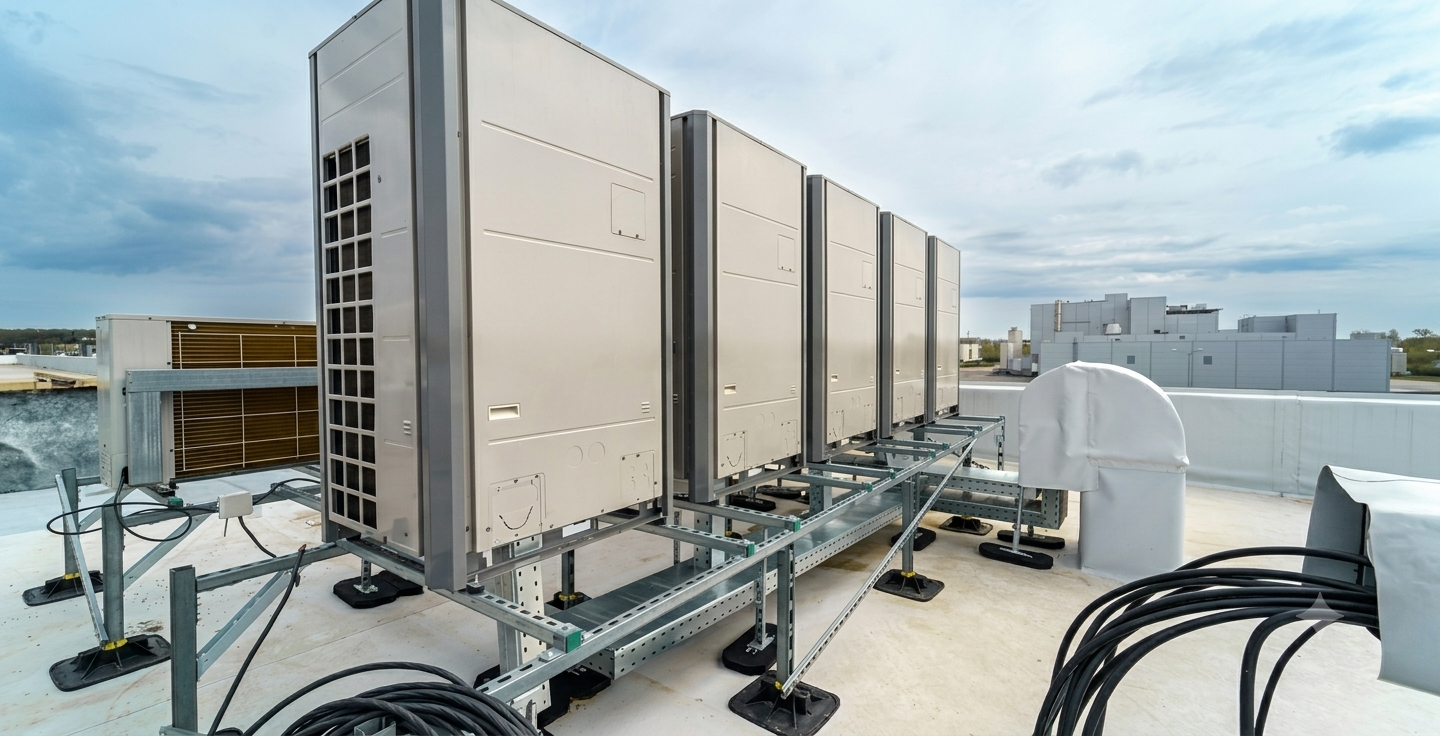
An hvac load calculation service delivers the foundational thermodynamic analysis necessary to engineer safe, efficient, and code-compliant climate control systems. Across modern commercial, industrial, and residential real estate, heating, ventilation, and air conditioning (HVAC) infrastructure accounts for 60% to 70% of a facility’s total energy consumption. Consequently, determining the exact sensible and latent thermal loads of a building is far more than a routine submittal for municipal building permits; it is a vital engineering discipline that dictates initial equipment capital expenditure, long-term operational costs, indoor air quality (IAQ), and decarbonization paths.
Relying on outdated rules of thumb—such as estimating cooling capacity based on generic square-footage ratios—introduces severe operational risks. Rules of thumb fail to account for building envelope orientation, dynamic fenestration Solar Heat Gain Coefficients (SHGC), high-density occupant metabolic loads, equipment plug densities, or localized ambient humidity. The resulting mis-sizing causes chronic compressor short-cycling, unhandled latent humidity, mold growth, premature mechanical failure, and inflated utility demand charges. Partnering with multi-disciplinary engineering specialists, such as the team at EngrTeam, ensures that every thermal load calculation accurately reflects physical building performance, environmental variables, and energy codes.
1. Thermodynamic Fundamentals Analyzed by an HVAC Load Calculation Service
A comprehensive hvac load calculation service evaluates the simultaneous transfer of sensible heat (temperature change) and latent heat (moisture phase change) across a building envelope. Mechanical cooling equipment must be sized to handle both heat types under dynamic outdoor weather conditions and internal usage schedules.
Sensible Heat (Qsensible)
- Temperature Changes
- Conduction, Convection & Radiation
Qs = 1.08 × CFM × ΔT
Latent Heat (Qlatent)
- Moisture & Relative Humidity
- Human Respiration & Air Infiltration
Ql = 4840 × CFM × ΔW
Sensible Thermal Gain Mechanics
Sensible thermal gains increase dry-bulb air temperature. They enter a space via conduction through walls, roofs, and floor slabs; convection at interior air-surface boundaries; and direct solar radiation through windows and skylights. The fundamental equation governing sensible heat transfer through volumetric air transport is:
Qs = 1.08 × CFM × (Toutdoor − Tindoor)
Where Qs represents the sensible heat transfer rate in British Thermal Units per hour (BTU/h), CFM denotes the volumetric airflow rate in cubic feet per minute, and ΔT = (Toutdoor − Tindoor) represents the dry-bulb temperature differential across the building boundary. The constant 1.08 is derived from the density of standard air (0.075 lb/ft³), the specific heat capacity of dry air (0.24 BTU/lb·°F), and a time conversion factor (60 min/h).
Conductive thermal gain through heavy exterior assemblies (such as multi-wythe brick, concrete masonry units, or tilt-up concrete panels) incorporates structural thermal storage via the Cooling Load Temperature Difference (CLTD) methodology:
Qconduction = U × A × CLTD
Where U is the overall thermal transmittance coefficient (BTU/h·ft²·°F), A is the exterior surface area (ft²), and CLTD adjusts standard dry-bulb temperature differences for structural thermal mass, solar absorption, and thermal time lag.
Direct and diffuse solar radiation through transparent fenestration is calculated using:
Qsolar = A × SHGC × IAC × CLF
Where SHGC is the Solar Heat Gain Coefficient, IAC is the Indoor Shading Coefficient, and CLF is the Cooling Load Factor, which models the delay between radiant solar absorption by interior surfaces and its convective release into room air.
Latent Thermal Gain Mechanics
Latent thermal gains result from moisture addition to interior air, increasing relative humidity and enthalpy without altering dry-bulb temperature. Primary latent sources include human metabolic respiration, ambient air infiltration through structural gaps, outdoor ventilation air, and specialized commercial processes. The mathematical expression governing latent heat transfer is:
Ql = 4840 × CFM × (Woutdoor − Windoor)
Where Ql is the latent heat exchange rate in BTU/h, and ΔW = (Woutdoor − Windoor) represents the humidity ratio differential in pounds of water vapor per pound of dry air (lbw/lbda). The constant 4840 incorporates standard air density, the latent heat of vaporization of water (≈ 1061 BTU/lb), and time unit conversions.
The total enthalpy differential (Qt) across a mechanical cooling coil reflects combined sensible cooling and moisture removal:
Qt = Qs + Ql = 4.5 × CFM × (houtdoor − hindoor)
Where h represents the specific enthalpy of moist air measured in BTU/lb of dry air.
The ratio of sensible heat to total heat dictates equipment coil selection through the Sensible Heat Ratio (SHR):
SHR = Qs / (Qs + Ql)
In humid climates where SHR drops below 0.70, cooling coils must be engineered for deep moisture removal, or supplemental dedicated dehumidification must be installed.
2. Standard Methodologies: ACCA Manual J/N vs. ASHRAE Radiant Time Series
Thermal calculation standards differ between residential and commercial occupancies. ACCA Manual J governs residential structures, while ACCA Manual N and ASHRAE Radiant Time Series (RTS) or Heat Balance (HB) methods govern multi-family, commercial, and healthcare facilities.
| Load Modeling Variable | ACCA Manual J (Residential) | ACCA Manual N & ASHRAE RTS (Commercial) | ASHRAE Standard 170 (Healthcare) |
| Occupancy Densities | Static low-density profiles (typically 2 to 6 occupants per home). | Dynamic multi-zone profiles with variable shift schedules. | High continuous occupancy with strict isolation suite controls. |
| Ventilation Mandates | Infiltration-driven combined with ASHRAE 62.2 baseline exhaust. | High outdoor fresh air supply rates per ASHRAE 62.1. | Up to 20+ total air changes per hour (ACH) with 100% outdoor air. |
| Plug & Appliance Loads | Standard appliance defaults and residential lighting densities. | Heavy internal gains from IT servers, office gear, and lighting panels. | Major heat rejection from imaging equipment, surgical lights, and sterilizers. |
| Diversity Factors | Minimal diversity applied due to uniform spatial utilization. | Diversity factors applied across lighting, plug, and occupancy zones. | Zero-diversity enforcement on critical surgical and isolation suites. |
| Pressure Gradients | Neutral or slightly positive envelope targets. | Zonal pressure balances designed to limit unconditioned infiltration. | Precise positive/negative directional pressure for infection control. |
3. Assessing Envelope Performance, Thermal Mass, and Air Infiltration
Envelope Thermal Transmittance (U-Values)
An engineering load evaluation analyzes overall thermal transmittance coefficients (U-values) for all exterior boundary assemblies. U-value is the mathematical inverse of the cumulative thermal resistance (Rtotal) of all material layers:
U = 1 / (Rfilm, inside + ΣRmaterials + Rcavity + Rfilm, outside)
High thermal mass materials—such as insulated concrete forms (ICF), multi-wythe brick, and structural concrete—exhibit significant thermal storage capacity. Solar heat absorbed by massive exterior walls during peak daylight hours is stored within the material mass and slowly re-radiated into the building interior hours later. This thermal time lag dampens peak cooling loads and shifts maximum cooling demand away from solar noon.
Air Infiltration and Envelope Air Leakage
Uncontrolled air infiltration through structural gaps, envelope penetrations, and door openings introduces major sensible and latent loads. Infiltration rates are quantified through blower door pressurization testing or calculated using empirical models like the Sherman-Grimsrud infiltration framework, which accounts for real-time indoor-outdoor temperature differentials and local wind speeds.
4. Internal Heat Vectors: Occupancy, Plug Loads, and Lighting Interconnections
Internal heat gains generated within conditioned spaces add directly to net cooling loads. An hvac load calculation service categorizes internal heat vectors into three primary areas:
Human Metabolic
- Sensible & Latent Heat
- Activity-Based Heat Output
Lighting Panels
- W × 3.412 × Ful × Fsa
- Aligns with NEC Load Calculations
Equipment Plugs
- Continuous Heat Draw
- Servers, VFDs & Process Equipment
Metabolic Heat Output: Human thermal dissipation depends on activity level. A seated office worker releases approximately 250 BTU/h sensible heat and 200 BTU/h latent heat (450 BTU/h total), whereas an individual exercising dissipates up to 635 BTU/h sensible and 965 BTU/h latent heat (1600 BTU/h total).
Lighting Heat Conversion: Electrical lighting heat is calculated from total connected wattage, usage factors, and luminaire allowance coefficients:
Qlighting = Wlighting × 3.412 × Ful × Fsa
Where Wlighting is connected lighting power in Watts, 3.412 converts Watts to BTU/h, Ful is the lighting use factor, and Fsa is the luminaire special allowance factor (accounting for power supply and driver heat losses). Lighting thermal gains directly influence electrical sub-panel sizing and National Electrical Code (NEC) panelboard schedules.
- Equipment Plug Loads: Computers, IT servers, process machinery, and commercial appliances reject continuous sensible heat into ambient air. Commercial kitchens require specialized heat gain evaluations that account for localized exhaust hood capture efficiencies and thermal radiation from appliances.
Projects requiring integrated mechanical and electrical panel sizing can leverage specialized electrical engineering services to align thermal heat gains with electrical distribution schedules.
5. Outdoor Air Ventilation and Latent Dehumidification Strategies
Maintaining safe indoor air quality and limiting carbon dioxide and volatile organic compounds (VOCs) requires minimum outdoor air ventilation rates per ASHRAE Standards 62.1 and 62.2. Introducing unconditioned outdoor air into the mechanical ventilation stream introduces substantial sensible and latent loads.
In warm, humid climates, untreated outdoor ventilation air can account for over 50% of the total latent load on a cooling coil. To control indoor humidity without overcooling interior spaces, modern mechanical engineering decouples fresh air treatment from indoor sensible cooling using Dedicated Outdoor Air Systems (DOAS). A DOAS unit cools incoming outdoor air below its dew point to remove moisture before delivering neutral, dry air to parallel sensible cooling terminals (such as VRF fan coil units or active chilled beams).
Technical guidance on ventilation design standards is maintained by ASHRAE Technical Resources.
6. The Systemic Risks of Equipment Mis-Sizing
The Penalties of Oversizing
Specifying equipment based on arbitrary safety margins or outdated square-footage estimates introduces major operational problems:
- Compressor Short-Cycling: Oversized systems satisfy dry-bulb temperature setpoints rapidly. Consequently, the system satisfies the thermostat and shuts down before the cooling coil reaches a steady condensation state. Moisture remains suspended in room air, driving relative humidity above 60% to 65% and encouraging mold and fungal growth.
- Excessive Capital Expenditure and Energy Demand: Equipment sized beyond peak thermal demands increases initial equipment procurement costs for larger chillers, compressors, electrical service panels, and distribution ductwork. Additionally, frequent motor starting cycles draw high electrical inrush currents, increasing utility peak demand charges kW and accelerating contactor and motor winding wear.
The Risks of Undersizing
Conversely, specifying equipment below peak thermal demands leads to system failure during peak cooling conditions. During maximum outdoor design temperatures, undersized equipment operates continuously without satisfying indoor cooling setpoints. Continuous overload operation elevates compressor motor winding temperatures, trips electrical overload breakers, accelerates mechanical failure, and results in occupant discomfort.
| Performance Metric | Oversized Equipment (>20%) | Properly Sized System | Undersized Equipment (<-10%) |
| Indoor Relative Humidity | Elevated (58% to 75% RH); severe mold risk. | Optimal (45% to 52% RH); controlled latent removal. | High during peak ambient conditions. |
| Compressor Run Cycles | Frequent short cycles (3 to 6 min runs). | Continuous, modulated part-load operation. | Continuous, unmodulated 100% run capacity. |
| Equipment Lifespan | Reduced by 30–40% due to start/stop stress [25]. | Maximized; operating within design parameters. | Reduced due to thermal overload and continuous wear. |
| Utility Costs | High peak demand spikes kW. | Optimized part-load energy consumption. | High continuous kWh consumption. |
7. Connecting Load Calculations to Duct Sizing and Airflow Distribution
Once net thermal loads are established, mechanical engineers calculate required supply airflow rates CFM:
CFMspace = Qs,space / [1.08 × (Tspace − Tsupply air)]
Where Tsupply air is typically designed at 55°F for standard chilled water or direct-expansion (DX) systems maintaining a 75°F room temperature setpoint (ΔT = 20°F).
The calculated airflow rates determine ductwork sizing, diffuser placement, and static pressure drop calculations across the distribution network. Using equal-friction or static-regain duct design methods, engineers map out supply, return, and exhaust duct layouts, ensuring air velocities remain within acceptable noise criteria thresholds (e.g., 1,000 to 1,500 FPM in main commercial ducts, 600 to 800 FPM in branch ducts).
Inaccurate load estimations compromise duct velocity profiles, leading to high static pressure losses, motor overload, or excessive air noise. Project teams seeking coordinated duct routing solutions can explore dedicated HVAC layout plan services.
8. 3D BIM Integration, Revit MEP, and Multi-Disciplinary Clash Detection
Modern mechanical engineering uses Building Information Modeling (BIM) software, such as Autodesk Revit MEP, linked with advanced energy simulation engines like EnergyPlus, eQuest, and IESVE. BIM creates an integrated spatial environment where architectural geometry, material thermal properties, room volumes, and fenestration performance are extracted directly from the digital model.
Exporting load calculation results into 3D BIM coordination models enables comprehensive multi-disciplinary clash detection. Large mechanical ductwork, variable air volume (VAV) terminal units, chilled water pipes, and dedicated outdoor air ducts compete for limited overhead plenum space alongside structural framing, electrical cable trays, and fire sprinkler mains.
Using automated clash detection tools like Navisworks, engineers run spatial rule matrices that identify physical intersections (“hard clashes”) and clearance access violations (“soft clashes”) prior to field construction:
- Hard Clashes: Instances where components physically overlap, such as a main supply air duct running straight through a structural steel wide-flange beam.
- Soft Clashes: Situations where components interfere with required maintenance access or code-mandated clearances, such as blocking access to a VAV box controller or an inline fire damper.
Resolving spatial conflicts virtually during design takes minutes of engineering adjustments, whereas resolving the same conflict physically on the job site can lead to project delays, change orders, and wasted materials. Industry studies demonstrate that BIM clash detection workflows reduce field change orders by 30% to 40%. Fully integrated mechanical, electrical, and plumbing engineering can be implemented through comprehensive MEP plan services.
9. Regulatory Energy Codes, LEED Certification, and Decarbonization Targets
Building codes—including the International Energy Conservation Code (IECC) and ASHRAE Standard 90.1—establish strict efficiency standards for building design. These codes restrict arbitrary equipment oversizing by capping design safety factors. Under these standards, engineers must limit safety factor multipliers to a maximum of 1.15 for sensible cooling capacity and 1.25 for heating capacity over calculated peak loads.
Energy & Atmosphere Credits
- Earns up to 33 LEED points
- Validates IECC Code Compliance
Decarbonization Alignment
- Optimizes Heat Pump / VRF Sizing
- Reduces On-Site Fossil Fuel Use
Precise thermal load calculations form the technical baseline for projects seeking Leadership in Energy and Environmental Design (LEED v4.1) certification through the USGBC. The Energy and Atmosphere (EA) category represents the largest block of available points in the LEED rating system. Engineers run energy simulations compliant with ASHRAE 90.1 Appendix G to demonstrate energy cost reductions compared to standard baseline buildings.
Accurate load calculations support sustainable outcomes by:
- Reducing annual operational energy consumption and carbon emissions.
- Facilitating the integration of high-efficiency systems, such as variable refrigerant flow (VRF), active chilled beams, and energy recovery ventilators (ERV).
- Optimizing the sizing of on-site solar photovoltaic (PV) arrays and battery energy storage systems (BESS) to achieve net-zero energy targets.
10. Specialized Load Sizing: Coastal Environments, Historic Retrofits, and Logistics Hubs
Coastal and Marine Environmental Protection
Executing mechanical engineering in coastal and marine environments introduces two major challenges: extreme ambient relative humidity combined with corrosive atmospheric salt aerosols. Airborne salt spray contains chloride ions that form conductive electrolyte films on exposed metal heat exchangers.
Galvanic corrosion accelerates at contact points between dissimilar metals—such as copper refrigerant tubes mechanically expanded into aluminum cooling fins. Pitting corrosion penetrates thin copper tube walls, causing refrigerant leaks, capacity loss, and total equipment failure within 3 to 5 years if left unprotected.
To protect heat exchanger coils without restricting airflow or increasing static pressure drop, equipment operating in marine environments requires factory-applied protective coatings. Advanced polyurethane coatings—such as Blygold PoluAl XT—are applied at precise dry film thicknesses. These coatings withstand over 11,000 hours of continuous salt spray testing under ASTM B117 standards, extending equipment service life while maintaining nominal heat transfer performance.
Adaptive Reuse and Historic Buildings
Repurposing historic or legacy buildings for modern commercial or residential use introduces unique thermal modeling variables. Older structures often feature uninsulated multi-wythe masonry walls that exhibit high thermal inertia. Thick brick or stone walls delay heat penetration, as detailed in National Park Service (NPS) Preservation Brief 24.
Applying standard steady-state heat transfer equations overestimates daytime peak cooling requirements. Dynamic load modeling must account for this thermal mass delay to prevent specifying oversized equipment. Furthermore, historic preservation codes prohibit damaging original plasterwork or masonry facades, requiring compact distribution networks like VRF systems or micro-ducts.
Large Logistics Warehouses and Fulfillment Centers
Logistics hubs with clear ceiling heights ranging from 30 to 50 feet experience severe vertical thermal stratification. Warm air naturally rises toward the roof deck, establishing a vertical temperature gradient of 0.5°F to 1.0°F per foot of elevation. In a 45-foot-tall facility, ambient temperatures near the ceiling can exceed floor-level temperatures by over 20°F.
To manage this thermal gradient, an hvac load calculation service models High-Volume Low-Speed (HVLS) destratification fans operating alongside rooftop units (RTUs) or VRF systems. HVLS fans continuously circulate air masses at low velocities, equalizing temperatures across vertical rack profiles and reducing annual heating and cooling energy usage by up to 30%.
Actionable Steps for Building Owners and Developers
Investing in a precise hvac load calculation service is a proven strategy for ensuring long-term operational performance, occupant comfort, and cost control. Developers and facility managers can maximize project success by following key engineering recommendations:
- Avoid Generic Rules of Thumb: Mandate that all heating and cooling equipment be sized using verified hourly load calculations (ACCA Manual J/N or ASHRAE RTS) rather than square-footage estimates.
- Decouple Sensible and Latent Loads in Humid Climates: Specify Dedicated Outdoor Air Systems (DOAS) to handle outdoor air dehumidification independently from indoor sensible cooling terminals.
- Enforce BIM-Driven Clash Detection: Integrate mechanical drawings into a 3D BIM coordination model to resolve spatial conflicts with structural and electrical trades prior to on-site construction.
- Protect Coastal Investments: Require factory-applied C5-M marine corrosion coatings (such as Blygold) on heat exchanger coils installed within coastal or high-salinity zones.
- Align Mechanical Sizing with Electrical Infrastructure: Ensure continuous mechanical motor loads are calculated at 125% per NEC guidelines when sizing electrical switchgear and distribution panels.
By implementing these engineering practices, building owners ensure their facilities operate with high energy efficiency, low lifecycle operating costs, and full code compliance.







