

Articles

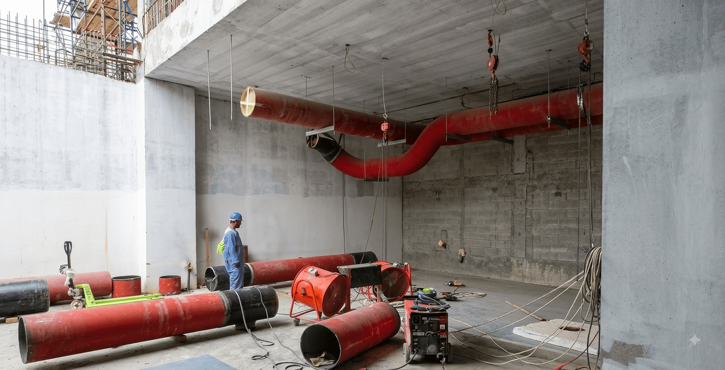
In modern architectural engineering, complete mepf design packages for buildings serve as the definitive technical blueprint for safe, resilient, and energy-efficient built environments. Mechanical, Electrical, Plumbing, and Fire Protection (MEPF) systems constitute the complex network of artificial lifelines that regulate indoor climate, distribute high-voltage electrical energy, deliver potable water, dispose of sanitary waste, and safeguard human life from environmental and fire hazards. In major commercial, industrial, healthcare, and high-density residential developments, building services account for 30% to over 50% of total construction capital expenditure and up to 80% of long-term operational expenses. Consequently, fragmented or uncoordinated drafting practices introduce unacceptable risks, including site-level trade clashes, unexpected change orders, permit rejections, and premature equipment degradation. Professional engineering platforms, including specialized engineering resources available at EngrTeam, demonstrate that consolidating all building services into unified digital models mitigates field rework, streamlines authority approvals, and enhances long-term facility performance.
The Engineering Scope of Complete MEPF Design Packages for Buildings
The production of an authoritative engineering package requires moving beyond isolated discipline drafting into holistic spatial design integration. Historically, mechanical engineers, electrical consultants, and plumbing designers produced two-dimensional CAD drawings independently. This legacy approach regularly resulted in spatial collisions on the job site—such as supply air ducts intersecting structural concrete beams or domestic water lines competing with electrical busducts in tight ceiling plenums. Modern construction management resolves these systemic inefficiencies by mandating specialized MEP plan services that combine all physical, mechanical, and electrical components into a singular, synchronized data environment.
An integrated MEPF package bridges the gap between conceptual architectural vision and constructible reality. By establishing physical routing parameters, maintenance access zones, equipment clearances, and structural penetrations during early design phases, project teams prevent retrofits during the construction phase. Furthermore, unified MEPF engineering supports long-term operational resilience. Sizing HVAC systems to match thermal envelope profiles, calculating precise electrical demand loads with appropriate diversity factors, and modeling hydraulic networks for fire suppression ensure that the completed asset complies with regional building safety codes while achieving maximum energy efficiency.
Mechanical and HVAC Engineering Systems in Complete MEPF Design Packages for Buildings
Mechanical engineering forms the backbone of thermal comfort, indoor air quality (IAQ), and energetic performance within a facility. Design procedures begin with granular heating and cooling load calculations per the American Society of Heating, Refrigerating and Air-Conditioning Engineers standards. Sensible heat gain calculations rely on fundamental thermodynamic formulations:
Qₛₑₙₛᵢᵦₗₑ = 1.08 × CFM × ΔT
where Qₛₑₙₛᵢᵦₗₑ represents heat transfer in British Thermal Units per hour (BTU/h), CFM denotes volumetric airflow rate in cubic feet per minute, and ΔT represents the temperature differential in degrees Fahrenheit across the coil or zone. Simultaneously, latent heat gain from occupant moisture and outdoor air infiltration is evaluated using psychrometric enthalpy state points:
Qₗₐₜₑₙₜ = 4840 × CFM × ΔW
where ΔW signifies the humidity ratio differential in pounds of water per pound of dry air. Integrating HVAC layout plan documentation ensures that air distribution networks are sized using velocity and static pressure drop methods to minimize fan energy and acoustic disturbance.
Ductwork sizing calculations utilize SMACNA velocity schedules, maintaining main distribution duct velocities between 1200 fpm and 1800 fpm for commercial spaces to balance friction losses against duct surface area. Hydronic system designs evaluate pipe pressure drops using the Hazen-Williams formulation:
p꜀ = (4.52 × Q¹·⁸⁵) / (C¹·⁸⁵ × d⁴·⁸⁷)
where p꜀ is friction loss per foot of pipe, Q is fluid flow rate in gallons per minute, C is the pipe roughness coefficient, and d is internal pipe diameter in inches. The mechanical framework encompasses central plant equipment selection—such as air-cooled or water-cooled chillers, cooling towers, condensing boilers, primary/secondary pumping loops, air handling units (AHUs), fan coil units (FCUs), variable refrigerant flow (VRF) networks, and variable air volume (VAV) terminal boxes—alongside complete ductwork and hydronic piping schematics. Specialized air distribution requirements, including dedicated outdoor air systems (DOAS) and kitchen or stairwell smoke pressurization systems, are integrated to ensure occupant safety and strict adherence to ventilation standards.
Electrical and Low-Current Infrastructure in Complete MEPF Design Packages for Buildings
Electrical engineering designs power delivery mechanisms, artificial illumination, emergency backup solutions, and extra-low voltage (ELV) communication networks. Engineers execute comprehensive load flow analyses, short-circuit calculations, and voltage drop evaluations to size high-voltage (HT) and low-voltage (LT) transformers, diesel generators, main switchboards, busducts, and panelboards. Incorporating electrical engineering services allows design teams to precisely establish feeder sizes, breaker interrupting capacities, and protective device coordination.
Feeder sizing and breaker selection mandate rigorous evaluation of continuous and non-continuous electrical loads. Voltage drop across continuous three-phase distribution feeders is limited to 3% for branch circuits and 5% total for combined feeders and branch circuits per energy conservation codes, evaluated via:
Vᵈʳᵒᵖ = (√3 × I × L × (R cos θ + X sin θ)) / 1000
where I represents load current in amperes, L represents one-way conductor length in feet, R represents conductor resistance, X represents inductive reactance, and cos θ represents the load power factor.
In modern facilities, electrical design extends far beyond basic power circuits. It encompasses advanced lighting power density (LPD) compliance under energy codes, automated lighting control networks, grounding and lightning protection systems, and uninterruptible power supply (UPS) configurations for mission-critical infrastructure. Simultaneously, low-current engineering provides detailed schematics for building management systems (BMS), security access control, closed-circuit television (CCTV), telecommunications infrastructure, and fire detection networks governed by the National Fire Protection Association.
Plumbing and Public Health Engineering in Complete MEPF Design Packages for Buildings
Plumbing engineering manages the collection, treatment, delivery, and discharge of water-based fluids throughout the building lifecycle. Domestic cold and hot water systems are engineered using fixture unit calculations (Hunter’s Curve methodology) to determine peak demand flow rates, booster pump head requirements, water heater capacities, and hydrostatic pressure zones. Fluid velocity within distribution pipework is maintained between4 fps and 8 fps using the continuity equation:
Q = A × V
where Q represents volumetric fluid flow rate (m³/s or GPM), A represents internal pipe cross-sectional area (m² or in²), and V signifies fluid velocity (m/s or ft/s).
Sanitary drainage systems are modeled with fixed gravity slopes according to the International Plumbing Code (IPC) or Uniform Plumbing Code (UPC) to prevent solids deposition and siphonage. Drainage stacks are sized based on Drainage Fixture Units (DFU), incorporating pneumatic vent pipes to maintain atmospheric pressure equilibrium across trap seals. The public health engineering framework incorporates soil, waste, and vent stacks, grease traps, storm water detention systems modeled using the rational runoff method:
Q = C × I × A greywater recycling plants, and specialized fuel gas piping infrastructure where required.
Fire Protection and Life Safety Integration in Complete MEPF Design Packages for Buildings
Fire protection engineering constitutes the vital fourth pillar of life safety in built structures. Hydraulic calculation models dictate pipe sizes, pump room layouts, and water storage tank capacities required to supply automatic sprinkler systems, wet/dry standpipes, and fire hydrants. Sprinkler head discharge density is evaluated via the nozzle discharge equation:
Q = K × √P
where Q represents discharge flow rate in gallons per minute (GPM), K represents the sprinkler head discharge coefficient (K-factor), and P represents effective operating pressure in pounds per square inch (psi).
Design documentation specifies the location of alarm check valves, zone control valves, tamper switches, fire department connections (FDC), and specialized clean-agent gaseous suppression systems (such as FM-200 or Novec 1230) for data centers and electrical switchgear rooms. All layouts strictly adhere to standards established by the National Fire Protection Association, including NFPA 13, NFPA 14, and NFPA 20.
Level of Development Milestones in Complete MEPF Design Packages for Buildings
To achieve high precision in digital building models, complete MEPF design packages for buildings rely on standardized Level of Development (LOD) frameworks. Defined by the American Institute of Architects (AIA) and detailed across international BIM standard protocols, LOD specifies the degree to which a system element’s geometry, spatial location, and attached informational data can be relied upon by project stakeholders.
During initial conceptual design (LOD 100 and LOD 200), mechanical and electrical elements are represented as generic spatial masses or approximate layout zones. As the engineering design transitions into detailed design development (LOD 300), components are accurately sized and positioned with exact geometric parameters, system types, and physical connections. Fabrication and installation phases require LOD 350 and LOD 400 models, which include detailed mounting brackets, duct sheet metal gauges, pipe connection flanges, spool sheets, and manufacturer-specific equipment clearances required for prefabrication. Finally, the handover phase culminates in LOD 500 as-built models integrated with asset tracking metadata for long-term facility management.
| MEPF Discipline | LOD 200 (Schematic Layouts) | LOD 300 (Design Development & Code Validation) | LOD 350 (Cross-Trade Construction Interfaces) | LOD 400 (Off-Site Prefabrication & Spooling) | LOD 500 (As-Built Handover & Asset Management) |
| Mechanical (HVAC) | Generic space allocation for air handlers and main duct routes. | Accurate duct sizing, air terminal placements, and chiller connections. | Connection interfaces, seismic bracing, hanger locations, wall penetrations. | Sheet metal gauges, flanges, damper linkages, hangers, and spool sheets. | Field-verified model with serial numbers, warranty data, and maintenance logs. |
| Electrical Systems | Approximate distribution panel zones and cable tray runs. | Modeled switchgear, panel schedules, exact conduit paths, and light fixtures. | Exact raceway supports, pull box locations, transformer clearances. | Detailed busbar connections, junction boxes, support brackets, and wire counts. | As-commissioned power circuits, breaker trip settings, and panel balance data. |
| Plumbing Systems | Conceptual pipe riser locations and generic fixture counts. | Exact pipe diameters, slope angles, trap locations, and pump head duty points. | Pipe hanger spacing, sleeve penetrations through structural slabs. | Prefabricated pipe spools, connection unions, hangers, and valve tag numbers. | Laser-scanned field locations, valve schedules, and operational pressure logs. |
| Fire Protection | Conceptual main sprinkler line locations and pump room massing. | Hydraulically calculated pipe sizing, head coverage, and valve assemblies. | Structural attachment points, pipe drops around air ducts, sleeve locations. | Exact sleeve penetrations, hanger assemblies, grooved couplings, and drop nipples. | Verified sprinkler head coordinates, hydro-test reports, and compliance tags. |
Spatial Coordination and Clash Detection in Complete MEPF Design Packages for Buildings
The primary benefit of digitizing complete MEPF design packages for buildings lies in the execution of rigorous 3D spatial coordination and automated clash detection. Modern building spaces—particularly high-density ceiling plenums, vertical utility risers, and central plant rooms—contain thousands of interconnected mechanical, electrical, and plumbing elements competing for limited volume.
Through advanced federation of independent trade models in platforms like Autodesk Navisworks Manage, Solibri, or Revizto, engineering teams perform rule-based spatial audits before site mobilization. Detailed technical evaluations published in industry benchmarks, such as AMC Engineer clash detection guides, emphasize that rule-based clash engines compare exact geometry and clearance boundaries across three distinct clash classifications:
- Hard Clashes: Direct physical intersections where two distinct building components occupy the identical 3D coordinate space—such as a chilled water pipe passing through a structural steel beam or a major air duct contacting an electrical cable tray.
- Soft or Clearance Clashes: Spatial violations where an element encroaches upon required operational, insulation, maintenance, or safety access clearance zones—such as an air handler positioned too close to a wall, preventing filter removal, or a cable tray blocking an electrical panel working clearance dictated by the National Electrical Code.
- Workflow or 4D Clashes: Temporal and sequencing conflicts identified when linking the 3D model with the project construction schedule—such as scheduling heavy plant equipment installation after surrounding access walls have already been sealed.
The coordination cycle follows an eight-step iterative process: model federation, selection set creation, clash rule and tolerance definition, test execution, triage and classification, issue assignment to responsible trade leads via Building Collaboration Format (BCF), trade re-modeling, and final re-testing prior to sign-off. Adhering to a strict priority hierarchy—giving precedence to gravity drainage fall requirements and heavy structural members over smaller pressure piping and flexible conduits—ensures structured issue resolution.
| Discipline Pair | Primary Clash Mechanism | Standard Clearance Tolerance | Triage Priority Tier | Resolution Protocol |
|---|---|---|---|---|
| Mechanical vs. Structure | Ducts or chilled water mains passing through structural beams or slabs. | 25 mm (1 in) clear envelope or sleeve specification. | Priority 1 (Highest) | Structural geometry remains fixed; reroute ductwork or design engineered sleeve openings. |
| Mechanical vs. Electrical | Air ductwork intersecting cable trays, busducts, or lighting fixtures. | 50 mm (2 in) clearance above electrical components. | Priority 2 | Relocate electrical conduits or adjust air duct elevation profiles. |
| Mechanical vs. Plumbing | Ductwork colliding with sloped drainage lines or domestic water mains. | 25 mm (1 in) insulation clearance buffer. | Priority 2 | Gravity drainage fall parameters must be maintained; reroute pressure ductwork. |
| Electrical vs. Plumbing | Cable trays running directly beneath uninsulated wet piping networks. | 150 mm (6 in) vertical separation distance. | Priority 1 (Life Safety) | Shift cable trays above wet piping or establish water-deflecting drip trays. |
| Fire Protection vs. HVAC | Sprinkler branch lines clashing with supply/return duct branches. | 50 mm (2 in) clear spray pattern distance. | Priority 3 | Offset flexible sprinkler drops or modify local duct elevation drops. |
Information Management and ISO 19650 Protocols in Complete MEPF Design Packages for Buildings
Managing complex data structures within complete MEPF design packages for buildings requires adherence to global information management benchmarks, notably the ISO 19650 series. ISO 19650-1 and ISO 19650-2 govern the delivery phase of built assets, establishing standardized procedures for generating, validating, and distributing digital building information across all project participants.
Central to ISO 19650 compliance is the execution of a Common Data Environment (CDE). The CDE acts as a single, controlled digital repository where building services data flows through four distinct gatekeeping states:
- Work in Progress (WIP): Unapproved discipline-specific design updates generated by individual mechanical, electrical, or plumbing engineering teams.
- Shared: Checked design models released for multi-disciplinary coordination, spatial clash analysis, and consultant review.
- Published: Fully coordinated, client-approved models and drawing sets authorized for construction, prefabrication, and statutory authority permitting.
- Archived: Formally stored historical records reflecting baseline design iterations and final as-built project documentation.
Establishing clear BIM Execution Plans (BEPs), uniform naming conventions, standardized parameter sets, and shared origin coordinate systems prevents model misalignment and guarantees spatial accuracy across all engineering documentation.
Regulatory Standards and Multi-Code Auditing in Complete MEPF Design Packages for Buildings
Engineering complete MEPF design packages for buildings demands strict compliance with regional building codes and international technical standards. Mechanical, electrical, and plumbing engineering designs touch more regulatory codes than any other construction discipline. Design documents must demonstrate full alignment with prescriptive performance mandates, safety factors, and material guidelines established by major standards organizations.
For mechanical systems, design teams consult ASHRAE technical guidelines for energy efficiency and indoor air quality benchmarks, alongside Sheet Metal and Air Conditioning Contractors’ National Association guidelines for duct construction gauges and reinforcement. Electrical installations must conform strictly to the National Electrical Code (NEC / NFPA 70) and International Electrotechnical Commission guidelines to guarantee short-circuit protection and personnel safety. Plumbing designs conform to the International Plumbing Code (IPC) and International Mechanical Code (IMC), while fire protection systems must comply with comprehensive National Fire Protection Association (NFPA) codes.
| Building System | Governing Codes & Standards | Technical Design Parameters Governed | Critical Automated Audit Metrics |
|---|---|---|---|
| HVAC & Ventilation | ASHRAE 62.1, ASHRAE 90.1, IMC, SMACNA | Outdoor air intake rates, fan power limitations, duct static pressure loss, thermal envelope efficiency. | Outdoor air CFM per occupant, duct sheet metal gauge compliance, equipment COP/EER ratings. |
| Electrical Power | NEC (NFPA 70), IEC 60364, IEEE 1547 | Busbar sizing, cable ampacity ratings, transformer grounding, panel working clearances. | Working clearance depths (3 ft min), feeder overload protection, maximum 3% voltage drop. |
| Plumbing & Sanitary | IPC, UPC, ASPE Data Books | Drainage pipe slope angles, fixture unit calculations, vent pipe height, backflow prevention. | Drainage slope angle (1/4 in/ft min), vent terminal height above roof line (12 in min). |
| Fire Suppression | NFPA 13, NFPA 14, NFPA 20, NFPA 72 | Sprinkler density zones, fire pump head curves, standpipe pressure limits, alarm detector spacing. | Smoke detector grid spacing (30 ft max), sprinkler obstruction distance rules. |
Essential Deliverables Included in Complete MEPF Design Packages for Buildings
A construction-ready MEPF design package consists of a detailed set of graphical and non-graphical deliverables. These documents provide contractors, fabricators, and municipal approval authorities with complete clarity regarding system configurations, routing, operational parameters, and material quantities.
Basis of Design Reports and Technical Specifications
Basis of Design (BOD) reports articulate the core design philosophy, indoor and outdoor ambient design thresholds, utility load requirements, system selection justification, safety factors, and applicable building code editions. Technical specifications define material quality metrics, installation techniques, testing protocols, and commissioning requirements.
Schematics, Single-Line Diagrams, and Riser Diagrams
Schematic diagrams establish the logical connection framework for complex building services without spatial scale constraints. Key schematics include:
- Electrical Single-Line Diagrams (SLDs): Illustrative representations showing main incoming utility feeds, switchgear configurations, transformer ratings, automatic transfer switches (ATS), generator feeds, distribution panels, and circuit breaker sizes.
- Plumbing and Fire Protection Riser Diagrams: Vertical representations detailing soil, waste, and vent pipe sizes across floor levels, static pressure zoning, backflow preventer placements, and firefighting standpipe connections.
- HVAC Control and Piping Schematics: Piping and Instrumentation Diagrams (P&IDs) illustrating chilled water loop configurations, primary/secondary pump connections, control valve arrangements, and sequence of operation logic.
Coordinated Layout Drawings and 3D Federated BIM Models
Floor plan drawings scaled to appropriate project standards represent the exact horizontal and vertical coordinates of all building services components. Modern design packages feature fully coordinated 3D BIM models exported in open formats (such as IFC) alongside native software files. Specialized drawings include enlarged plant room layouts, section cuts through dense service corridors, structural sleeve penetration plans, and reflected ceiling plans (RCP) showing lighting, diffusers, and sprinkler heads.
Shop Drawings, Spool Sheets, and Bill of Quantities
For projects transitioning into construction and assembly phases, packages provide trade-specific shop drawings derived from LOD 400 BIM models. Pipe spool drawings provide precise spool lengths, weld locations, and fitting angles to facilitate off-site prefabrication. Simultaneously, integrated software tools extract precise Bills of Quantities (BOQ) detailing total linear duct meterage, pipe lengths, fixture counts, cable tray weights, and major equipment schedules to support cost control.

Life-Cycle ROI and Sustainable Integration in Complete MEPF Design Packages for Buildings
Investing in rigorous MEPF engineering packages yields direct financial and environmental dividends across a building’s lifecycle. Upfront coordination significantly reduces change orders during construction—which historically represent up to 10% of total project costs—by resolving physical interferences virtually.
From a operational perspective, energy-modeled HVAC and lighting systems reduce annual utility consumption, aligning facilities with green building certifications such as LEED and BREEAM. Furthermore, incorporating spatial accessibility zones into 3D models ensures that filters, valves, motors, and panels can be routinely serviced without damaging adjacent finishes, thereby extending asset longevity and maintaining high indoor air quality.
Strategic Execution of Complete MEPF Design Packages for Buildings
The evolution of modern facility development demands a fundamental shift in how building services are conceptualized, engineered, and executed. Commercial, healthcare, industrial, and high-density residential developments can no longer tolerate the spatial inefficiencies, site rework, and inflated lifecycle costs associated with uncoordinated or incomplete engineering documentation. Delivering complete MEPF design packages for buildings through synchronized 3D BIM workflows, strict ISO 19650 information management, and multi-code compliance forms the absolute cornerstone of successful contemporary construction.
By unifying advanced engineering calculation methodologies—including thermodynamic energy simulations, hydraulic distribution modeling, automated 3D clash triage, and prefabrication spool generation—project stakeholders ensure that building systems operate with peak efficiency, superior occupant comfort, and uncompromising life safety. As the built environment continues to adopt intelligent microgrids, high-power electric vehicle infrastructure, smart building automation networks, and aggressive carbon neutrality targets, high-fidelity MEPF engineering packages will remain the central driver of sustainable, high-performance architecture.







