

Articles

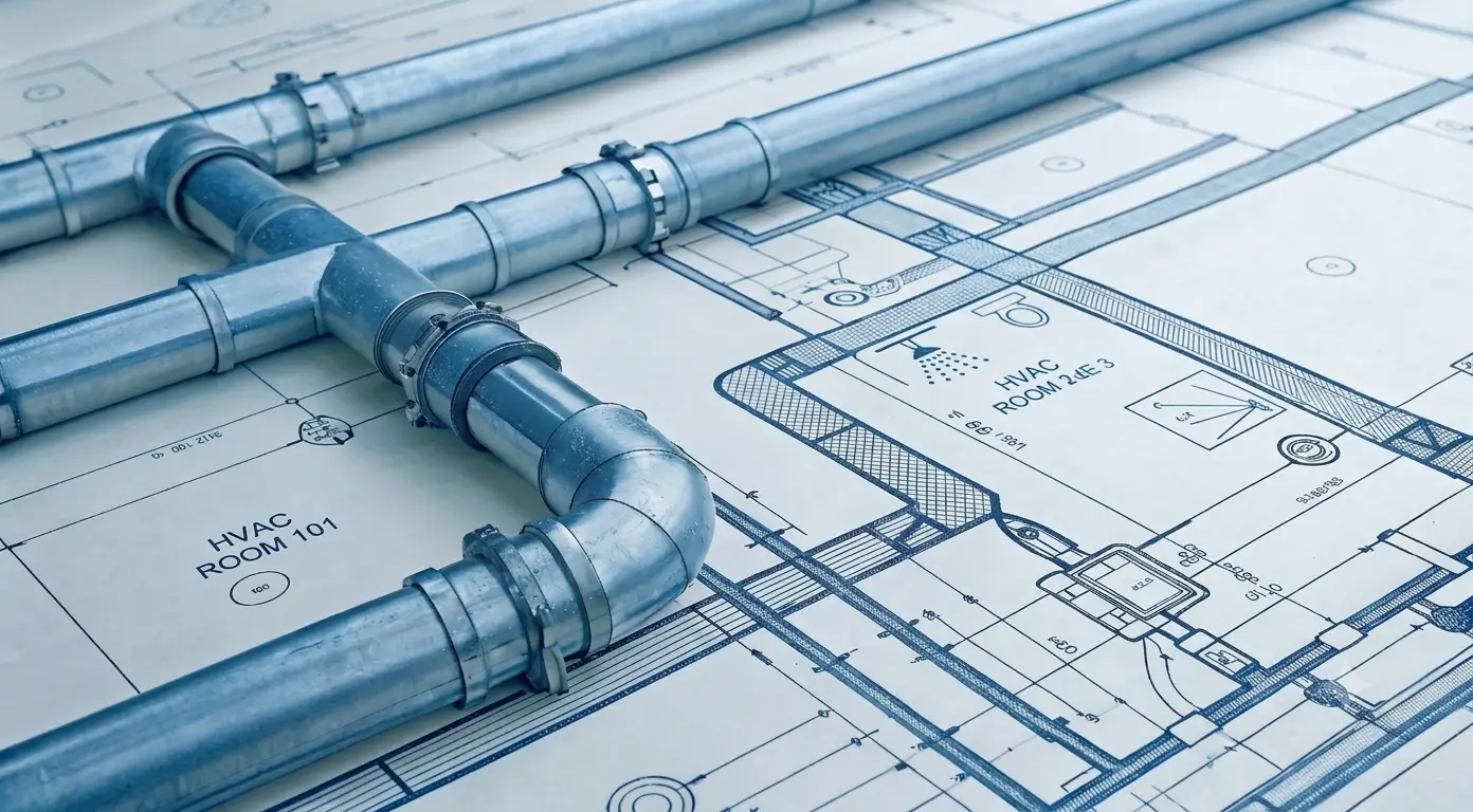
Modern commercial infrastructure relies on plumbing system design to safeguard public health, ensure structural integrity, and optimize operational efficiency. Executing a high-performance fluid conveyance network requires meticulous engineering analysis, dynamic spatial coordination, and multidisciplinary integration. Plumbing systems serve as the biological and mechanical backbone of constructed assets, delivering potable water at precise volumetric rates while removing sanitary waste and managing stormwater without compromising indoor air quality or structural safety.
As commercial structures increase in scale and complexity, the engineering methodologies governing fluid mechanics, pipe sizing, pressure regulation, and digital coordination must evolve accordingly. Plumbing networks do not exist in isolation; they interact continuously with structural frameworks, electrical distribution grids, and mechanical ventilation systems. Engineering teams seeking comprehensive technical alignment across all building services rely on coordinated platform solutions, such as those provided by ENGR Team, to deliver fully integrated construction documentation through expert MEP plan services. A failure in engineering rigor during initial design phases can precipitate severe operational consequences, including erosion-corrosion, sewer gas migration, trap seal siphonage, water hammer, and hazardous microbial contamination such as Legionella pneumophila proliferation.
Hydraulic Mechanics and Fluid Sizing in Plumbing System Design
Calculating water demand in multi-story residential, commercial, and institutional facilities requires probabilistic modeling rather than assuming simultaneous maximum usage across all installed fixtures. The standard design methodology utilizes Water Supply Fixture Units (WSFU), a load factor that quantifies a fixture’s demand contribution based on its discharge rate, operation duration, and usage frequency. The cumulative WSFU load for a given pipe segment is converted into an estimated peak volumetric demand in gallons per minute (GPM) using Hunter’s Curve, which accounts for the non-linear probability of simultaneous fixture operation.
Plumbing Piping Velocity and Pressure Loss
Once the design flow rate is established, piping geometry is sized to maintain fluid velocity within a strictly controlled operational envelope, typically between 2 ft/s and 8 ft/s. Velocities below 2 ft/s allow suspended particulate matter to drop out of solution, leading to internal sedimentation and localized pipe fouling. Conversely, velocities exceeding 8 ft/s generate disruptive acoustic noise, induce violent water hammer pressure surges during valve closure, and accelerate erosion-corrosion along internal pipe walls and fitting transitions.
The dynamic pressure loss resulting from fluid friction against internal pipe walls is calculated using the Hazen-Williams equation:
hᶠ = 0.2083 × (100/C)¹·⁸⁵² × Q¹·⁸⁵² / d⁴·⁸⁶⁵⁵
Where:
- hᶠ represents the friction head loss expressed in feet of water per 100 feet of pipe (ft H₂O/100 ft).
- C denotes the Hazen-Williams roughness coefficient, varying from C = 150 for smooth thermoplastics (PEX, PVC) to C = 140 for copper tubing and C = 100 for aged cast iron.
- Q represents the volumetric flow rate in gallons per minute (GPM).
- d denotes the actual internal pipe diameter in inches (in).
In multi-story construction, static head loss adds 0.433 psi of pressure drop per vertical foot of elevation rise (0.098 bar/m). When municipal main pressure is insufficient to maintain the minimum residual fixture pressure—typically 15 to 35 psi depending on whether flushometer valves or standard tank fixtures are deployed—variable frequency drive (VFD) booster pump packages are required.
Conversely, when static elevation head accumulation causes system pressure to exceed 80 psi on lower floors, Pressure Reducing Valves (PRVs) must be installed in accordance with the International Plumbing Code (IPC) to protect fixture seals and control erosion.
| Commercial Fixture Category | Nominal Supply Connection (Inches) | Continuous Flow Rate (GPM) | Public WSFU Weighting | Private WSFU Weighting |
| Flushometer Water Closet | 1.00 | 25.0 to 35.0 | 10.0 | 6.0 |
| Tank-Type Water Closet | 0.50 | 3.0 to 5.0 | 5.0 | 3.0 |
| Public Lavatory Basin | 0.50 | 1.5 to 2.2 | 2.0 | 1.0 |
| Commercial Kitchen Sink | 0.50 | 4.0 | 4.0 | 2.0 |
| Emergency Deluge Eyewash | 1.00 to 1.25 | 20.0 to 30.0 | Direct Continuous Load | Direct Continuous Load |
| Flushometer Wall Urinal | 0.75 | 12.0 to 15.0 | 5.0 | N/A |
| Hospital Surgical Scrub Sink | 0.50 | 3.0 | 3.0 | N/A |
Sanitary Waste, Soil Venting, and Atmospheric Balance in Plumbing System Design
Unlike pressurized supply distribution networks, sanitary gravity drainage systems operate as open-channel unpressurized fluid networks. Horizontal soil and waste branches rely on continuous downward slopes to maintain liquid momentum, ensuring that fluid streams transport suspended organic solids without settling. Gravity flow velocity within sloped horizontal branches is evaluated using Manning’s Equation:
V = (1.486 / n) × Rₕ²ᐟ³ × S¹ᐟ²
Where:
- V represents the mean flow velocity expressed in feet per second (ft/s).
- n denotes Manning’s roughness coefficient, typically calibrated to 0.009 to 0.011 for smooth plastic or smooth-lined cast-iron piping.
- Rₕ is the hydraulic radius in feet (ft), calculated as the cross-sectional flow area divided by the wetted perimeter (A/P).
- S is the slope of the energy grade line expressed in feet of vertical drop per foot of horizontal run (ft/ft).
International plumbing standards dictate strict slope limits: horizontal pipes 2.5 inches or smaller require a minimum downward slope of 1/4 inch per foot (2%), while pipes between 3 inches and 6 inches require a minimum slope of 1/8 inch per foot (1%). Slopes steeper than 1/2 inch per foot must be avoided on long runs; excessive pitch causes liquid streams to accelerate and separate from heavier solids, stranding particulate matter and causing chronic blockages.
To prevent harmful sewer gases, volatile organic compounds, and pathogen-laden aerosols from entering occupied spaces, every plumbing fixture must be isolated by a P-trap providing a standing liquid water seal between 2 inches and 4 inches deep. However, as wastewater flows down vertical soil stacks, it creates rapid internal air pressure fluctuations. High-velocity falling water slugs induce negative pressure zones behind the fluid stream and positive backpressure zones at stack transitions where vertical flow impacts horizontal building drains.
Uncontrolled pressure differentials easily pull or push water out of P-traps, breaking the barrier seal. To prevent trap seal failure, engineers design continuous atmospheric venting networks. These venting networks equalize pressure across the drainage piping, maintaining internal system pressures within ±1 inch of water column relative to ambient atmospheric pressure. Common venting options include:
- Individual Venting: A dedicated vent pipe connects directly to the fixture drain downstream of the P-trap, rising vertically above the flood-level rim before tying into a central vent stack.
- Circuit Venting: A single vent pipe services a battery of up to eight fixtures on a horizontal branch drain, utilizing internal air space above the liquid flow line to maintain pressure balance.
- Stack Venting: The main vertical soil stack extends upward through the roof terminal, acting as the primary vent path for fixtures connected directly to the stack.
- Air Admittance Valves (AAVs): One-way mechanical valves that open under negative pressure to admit ambient room air into the drain pipe, closing by gravity under neutral or positive pressure. While AAVs eliminate complex roof penetrations, their deployment is subject to local code approvals and accessibility mandates for mechanical servicing.
Integrating Fire Protection Networks with Potable Water in Plumbing System Design
Connecting fire suppression systems to municipal potable water supplies creates a potential cross-connection hazard. Fire sprinkler networks contain stagnant water that may remain motionless within steel pipe grids for years, absorbing iron oxides, microbiological contaminants, or corrosion inhibitors. If municipal supply pressure drops significantly due to a water main break or heavy firefighting operations, back-siphonage can draw contaminated fire main water backward into the public drinking water supply.
Engineers eliminate backflow risks by installing mechanical backflow prevention assemblies at the system interface:
- Reduced Pressure Zone (RPZ) Assemblies: Comprising two independently acting check valves separated by a hydraulically operated differential relief valve, RPZs offer the highest level of protection against both back-siphonage and backpressure. If either check valve fails or pressure dynamics reverse, the internal relief valve vents fluid to the atmosphere, breaking the hydraulic link. RPZ units are mandatory on high-hazard cross-connections, such as fire networks utilizing chemical additives or foam concentrate.
- Double Check Detector Assemblies (DCDA): Standard for dedicated wet-pipe automatic fire sprinkler systems lacking chemical additives, DCDAs incorporate a low-volume bypass meter line to register unauthorized water use or slow system leaks while maintaining inline backflow protection.
Integrating fire pumps, jockey pressure maintenance pumps, supervisory alarm switches, and backflow devices requires close alignment with incoming electrical service feeds. Fire pump motors demand high electrical power capacity, dedicated transfer switches connected to emergency backup generators, and specialized controller panels compliant with NFPA 20 standards. Ensuring seamlessly coordinated electrical infrastructure for booster pumps, alarm panels, and automated shut-off systems requires partnering with multidisciplinary teams that provide specialized electrical engineering services alongside core plumbing calculations.
Advanced BIM Coordination and Spatial Clash Detection in Plumbing System Design
Modern construction relies on 3D Building Information Modeling (BIM) to transition plumbing schematics into precise spatial building models. Gravity drainage networks are particularly spatial-sensitive because pipe slope requirements strictly dictate vertical elevations and ceiling plenum utilization. Unlike flexible electrical conduits or small-diameter pressurized water pipes, sloped waste lines and large stormwater headers cannot easily alter their elevation or make abrupt turns around structural elements, shear walls, or mechanical ductwork.
BIM spatial coordination evolves through structured Levels of Development (LOD):
- LOD 200 (Concept Schematic): Generic spatial paths representing major piping mains, shaft locations, and equipment footprint zones.
- LOD 300 (Design Development): Accurate pipe diameters, exact slope angles, equipment models, and elevation anchors derived from hydraulic calculations.
- LOD 350 (Construction Coordination): Fully detailed models including pipe joints, mechanical couplings, insulation thickness, hanging hardware, seismic bracing, and structural sleeve penetrations.
- LOD 400 (Fabrication & Spooling): High-fidelity models containing manufacturer-specific fabrication geometry, prefabrication spool numbers, cut lengths, weld locations, and material bill-of-quantities.
- LOD 500 (As-Built Operations): Field-verified models updated post-construction to reflect exact installed conditions for facility maintenance and asset management.
Digital design teams utilize automated clash detection engines—such as Navisworks Manage, Solibri, and Revizto—to merge discipline models into a federated coordination space. As detailed in technical documentation on AMC Engineer BIM Clash Detection, spatial conflicts are categorized into three distinct types:
- Hard Clashes: Physical geometric intersections where a plumbing pipe passes directly through a structural beam, slab, wall, or mechanical duct without an approved sleeve or opening.
- Soft (Clearance) Clashes: Violations of required physical clearance zones, such as placing a uninsulated domestic water pipe too close to a hot exhaust duct or blocking clearance access needed to service a backflow valve or cleanout plug.
- 4D (Workflow) Clashes: Temporal construction conflicts where trade scheduling overlaps in the same physical zone, such as closing drywall partitions before overhead sloped drain mains are inspected.
To maintain order during coordination, teams follow strict trade priority hierarchies defined within the project’s BIM Execution Plan (BEP). Unpressurized gravity drainage networks hold top spatial priority due to their inflexible slope requirements. Large-scale supply and return air ductwork designed via tailored HVAC layout plans hold the next priority tier, while pressurized water pipes, sprinkler lines, and flexible electrical conduits are coordinated around these fixed MEP elements.
| Trade Building Discipline | Spatial Coordination Hierarchy | Minimum Maintenance Clearance Zone | Key Technical Constraint |
| Sanitary & Storm Gravity Drainage | Priority 1 (Highest Spatial Priority) | 2.0 inches around couplings/hubs | Fixed downward slope; non-negotiable elevation drops. |
| Large Sheet-Metal HVAC Ductwork | Priority 2 | 3.0 inches to structural steel | High volumetric profile within ceiling plenum. |
| Pressurized Water & Fire Suppression | Priority 3 | 1.5 inches insulation clearance | Can route around obstacles using 45° and 90° elbows. |
| High-Voltage Electrical Cable Tray | Priority 4 | 12.0 inches above wet piping | Safety codes prohibit un-enclosed wet lines directly over trays. |
| Lighting Conduits & Control Cabling | Priority 5 (Lowest Spatial Priority) | 1.0 inch field clearance | Highly flexible routing options during final field installation. |
Code Compliance, Regulatory Frameworks, and Standards in Plumbing System Design
Plumbing engineering is governed by strict local, national, and international safety codes. Designing compliant systems requires navigating overlapping regulatory frameworks enforced by regional Authorities Having Jurisdiction (AHJs). Core technical codes include:
- International Plumbing Code (IPC) / Uniform Plumbing Code (UPC): Prescribe legal baseline requirements for minimum fixture counts, pipe sizing, slope rules, venting configurations, backflow protection, and indirect waste receptors.
- International Building Code (IBC): Establishes occupancy classifications that dictate required male, female, and single-user accessible plumbing fixture counts.
- NFPA Standards (13, 14, 20, 22, 24): Govern automatic sprinkler system installations, standpipe hose connections, fire pump room layouts, water storage tanks, and private fire service mains.
- ASHRAE Standard 90.1 & Energy Conservation Codes: Mandate thermal performance levels for pipe insulation, hot water recirculation controls, temperature maintenance controls, and maximum standby heat losses for water heaters.
- ISO 19650 Standards: Define information management processes across the digital asset lifecycle using Common Data Environments (CDE) to manage design revisions and approval states.
To ensure full compliance before permit submission, engineering teams utilize multi-code verification workflows. Automated compliance checks cross-reference project parameters against regional amendments adopted by the local AHJ. For example, verifying that a roof vent penetration extends a minimum of above the finished roof surface—or higher in snow-load regions per IPC Section 904.1—prevents permit delays and costly site rework.
Material Science and Sustainable Conservation Strategies in Plumbing System Design
Modern plumbing engineering incorporates sustainable water management strategies to minimize water consumption and reduce lifecycle energy requirements. Commercial facilities increasingly incorporate greywater recycling and cooling coil condensate harvesting systems. Greywater—collected from lavatory basins, showers, and clothes washers—is treated using multi-stage filtration and membrane bioreactors (MBR) before being redistributed for toilet flushing and subsurface landscape irrigation. Cooling coil condensate yields pure, low-mineral water that can be directed to cooling tower makeup tanks, reducing municipal water demand during peak cooling seasons.

Energy efficiency in domestic hot water (DHW) generation requires balancing energy conservation with public health protection. Legionella pneumophila bacteria colonize in stagnant water environments within a temperature window of 68°F (20°C) to 122°F (50°C). To suppress bacterial growth, hot water generation and storage tanks must be maintained at 140°F (60°C) or higher. However, delivering water at 140°F directly to user fixtures presents severe scalding risks. Engineers resolve this conflict by placing point-of-use or master thermostatic mixing valves (TMVs) compliant with ASSE 1017/1070 standards downstream of storage tanks, blending 140°F water with cold supply lines to deliver a safe fixture temperature of 105°F to 120°F.
Continuous DHW recirculation loops powered by electronically commutated pumps ensure hot water is instantly available at distant fixtures, preventing water waste caused by users running taps while waiting for hot water.
Selecting piping materials requires evaluating working fluid temperatures, operating pressures, chemical water composition, fire-resistance ratings, acoustic properties, and life-cycle costs.
| Material Classification | Primary Piping Application | Operating Limit (°F) | Structural Strengths | Key Operational Limitations |
|---|---|---|---|---|
| Seamless Type K/L Copper | Domestic Hot & Cold Water Distribution | Up to 400°F | Exceptional pressure tolerance; natural antimicrobial surface; reliable press-fit or soldered joints. | Higher raw material costs; susceptible to pitting corrosion in low pH water (pH < 6.5). |
| Cross-Linked Polyethylene (PEX) | Branch Water Piping | Up to 200°F | Highly flexible; resists freeze-bursting; fewer mechanical fittings; rapid installation. | Degrades under direct UV light exposure; requires tight support spacing to prevent thermal sagging. |
| Schedule 40/80 PVC | Cold Water Supply, Storm Drain, Vents | Up to 140°F | Impervious to chemical corrosion; smooth inner surface (C = 150); highly economical. | Low thermal ceiling; combustible material requiring firestop collars at rated wall penetrations. |
| Hubless Cast-Iron Pipe | Soil, Waste, Vent, Storm Risers | Up to 212°F | Exceptional acoustic dampening; non-combustible fire rating; structural durability. | Heavy mass requires heavy-duty clevis hangers and vertical riser support clamps. |
| CPVC Thermoplastic | Hot & Cold Domestic Water | Up to 200°F | Higher thermal threshold than standard PVC; smooth interior surface; chemical resistance. | Requires specific solvent cements; can become brittle under extreme low-temperature mechanical impact. |
Lifecycle Optimization and Smart Infrastructure in Plumbing System Design
Long-term reliability depends on designing plumbing systems for ease of maintenance over the entire operational lifecycle of the building. Pumps, water heaters, backflow preventers, PRV stations, and drainage cleanouts require routine inspection, testing, and mechanical servicing. System layouts must provide adequate working clearances around mechanical equipment, incorporating access panels in permanent walls and ceilings wherever valves or mechanical devices are installed.
Integrating smart IoT sensors, automated acoustic leak detection meters, and motorized shut-off valves protects facilities from catastrophic water damage. Connected sensors continuously track pressure fluctuations, flow anomalies, and temperature variations, alerting facility engineers to sub-surface leaks, pump degradation, or freeze risks long before physical damage occurs.
Off-site prefabrication is transforming modern plumbing installation workflows. Developing coordinated LOD 400 models enables mechanical contractors to assemble modular multi-trade risers, pump skids, and fixture carrier assemblies within controlled factory settings. Prefabricated components are delivered directly to job sites for rapid assembly, reducing field labor costs, minimizing material waste, and improving job-site safety during high-rise construction.
Strategic Synthesis for Engineering Execution in Plumbing System Design
Achieving a high-performance, fully compliant plumbing system design requires combining core hydraulic principles, digital modeling workflows, and practical constructability awareness. From initial Water Supply Fixture Unit and peak flow calculations to continuous slope drain modeling and 3D clash coordination, every design decision directly impacts public safety, operational costs, and environmental efficiency.
Integrating multidisciplinary engineering solutions across plumbing, mechanical, and electrical trades eliminates spatial conflicts and ensures seamless permit approvals. Project teams can leverage the comprehensive engineering solutions available at ENGR Team to deliver fully coordinated building designs that optimize asset performance across every stage of construction and operation. Modern facilities can successfully minimize water usage, lower energy consumption, and guarantee safe fluid conveyance across their operational lifespan by grounding system layouts in robust engineering calculations, adhering to adopted building codes, and applying detailed BIM coordination processes.